
Videos
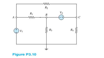
Use nodal analysis in the circuit of Figure P3.10 to find the voltages at nodes A, B, and C. Let
Want to see the full answer?
Check out a sample textbook solution
Chapter 3 Solutions
Principles and Applications of Electrical Engineering


- Consider the series-parallel circuit shown in the figure below with various multimeters connected in the circuit. Assum that XMM1 has been configured in ammeter mode, and XMM2 has been configured in voltmeter mode. XMM1 R1 1kQ XMM2 R2 R3 V1 1kQ 1kQ 12V 3.1: Redraw the circuit replacing XMM1 and XMM2 by their equivalent circuit models 3.2: Assume that XMM2 was incorrectly configured in ammeter mode. Redraw the equivalent circuit from 3.1 and compute the current that would be measured by the ammeter in this scenario. Hil-arrow_forwardQ3) For the network shown in the figure below, determine the following: a) fe b) Zinl and Zin2 c) Zo1 and Zo2 d) Avı, Av2, and AVT +20 V 6.8 kQ 30 ka 6.8 ka 30 ka 0.5 F 0.5 uF P-150 B- 150 1.5 ka 50 uF 1.5 ka 50 uFarrow_forwardQ3. The circuit to study is shown in figure below, where V1 = 100/0° V, V2 = 50/60° V, and R₁ = 3 Q, R₂ = 50, R3 = 2, R4 = 50, R5 = 50, L5 = 12.8 mH, L6 = 6.4 mH ,C₂= 796µF and C3=796uF assume f=50Hz V1 R1 R5 R2 + Vx & L5 Monote R3 L6 mo V2 C3 R4 a) Apply the mesh current method to obtain a complete set of circuit equations, presenting your answer in matrix form; b) Compute the potential across and the current flowing through the L6 elements.arrow_forward
- Q3: Suppose that the components of the circuit shown in figure below have the following values: RI= SkD, R2= 9kΩ, R3-10kΩ , R4-5kΩ, R5-10kΩ, R6-9k Ω. The voltage across AB is measured by a voltmeter whose internal resistance is 95k2. What is the measurement error caused by the resistance of the measuring instrument? R3 Rs RM Ri SMA Fo Em Ry Barrow_forwardUse the Principle of Superposition to determine the current i through R3 in the Figure. Let R1 = 100, R2 = 40, R3 = 20, R4 = 20, R5= 20, Vs 10 V, Is = 2A. ww VS R3 ww wwwarrow_forwardRefer to the given circuit below. Using Superposition Theorem, determine the percent contribution of E₁ to the current through R3 (lbc)- R3E1 % contribution = x 100 R3E1+1R3E2+¹R31 R1 R2 R3 R4 E₁ E2 T 8 Ω 6Q 4Q 7 V 11 V 5 A R₂ C ΤΩ R₁ E₁ a b R3 RA E₂arrow_forward
- 6. A Thevenin de equivalent circuit always consists of an equivalent.. a. AC voltage source b. capacitance c. DC voltage source d, resistance 7. The superposition theorem is useful for the analysis of. ***** a. single-source circuits. b. only two-source circuits. c. multi-source circuits. d. no source circuits.arrow_forwardO Given the information appearing in the Figure, Fird the level of resistance for Ri e R3. RI 3 o 14V Rgarrow_forward4) Use the Thevenin equivalent circuit technique to find Vab (a) without the load circuit connected (source circuit only) and (b) with the load circuit connected. (c) Using only one additional circuit element, to be connected across the ab terminals, sketch a circuit that would prevent the loading effect of the load circuit on the source circuit voltage. Please sketch this final circuit using the Thevenin equivalents from parts a and b. 3i1 SOURCE LOAD 2kN 3kN 2kN a 24V 4mA 8kQ 2k2 1kQ b 2000lxarrow_forward
- Refer to the given circuit below. Using Superposition Theorem, determine the percent contribution of I to the current through R3 (lbc). IR31 % contribution = x 100 1 +1 +1 R3E1 "R3E2 R3 R4 E1 E2 I 6Q 1Q 9 V 7V 3A a R31 R1 2Q R1 R2 1Q E₁ R2 C b R3 R4 E2arrow_forward8-13 E (a) Formulate mesh-current equations for the cir- cuit in Figure P3-13. (b) Formulate node-voltage equations for the circuit in Figure P3-13. (c) Which set of equations would be easier to solve? Why? (d) Using MATLAB, find , and i, in terms of the mesh- current variables. SSarrow_forwardDetermine r2 using product/sum rule. RT=40 ohms R1=200 ohms R2=? Solve using this equation "RT=(R1 X R2)/(R1+R2)" Also its a parallel circuitarrow_forward
 Introductory Circuit Analysis (13th Edition)Electrical EngineeringISBN:9780133923605Author:Robert L. BoylestadPublisher:PEARSON
 Delmar's Standard Textbook Of ElectricityElectrical EngineeringISBN:9781337900348Author:Stephen L. HermanPublisher:Cengage Learning
 Programmable Logic ControllersElectrical EngineeringISBN:9780073373843Author:Frank D. PetruzellaPublisher:McGraw-Hill Education
 Fundamentals of Electric CircuitsElectrical EngineeringISBN:9780078028229Author:Charles K Alexander, Matthew SadikuPublisher:McGraw-Hill Education
 Electric Circuits. (11th Edition)Electrical EngineeringISBN:9780134746968Author:James W. Nilsson, Susan RiedelPublisher:PEARSON
 Engineering ElectromagneticsElectrical EngineeringISBN:9780078028151Author:Hayt, William H. (william Hart), Jr, BUCK, John A.Publisher:Mcgraw-hill Education,