
Concept explainers
Videos
Apply nodal analysis to find io and the power dissipated in each resistor in the circuit of Fig. 3.64.
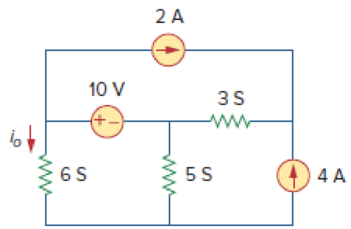
Figure 3.64
For Prob. 3.15.
Find the current
Answer to Problem 15P
The value of current
Explanation of Solution
Given data:
Refer to Figure 3.64 in the textbook for the nodal analysis. In the given circuit,
Calculation:
Modify the given figure with the representation of supernode and current direction as shown in Figure 1.
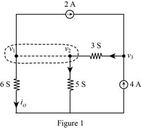
Apply Kirchhoff’s current law to the supernode in Figure 1.
Apply Kirchhoff’s current law to node
Reduce the given figure to provide voltage relation as shown in Figure 2.
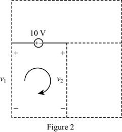
Apply Kirchhoff’s voltage law to the circuit in Figure 2 to get relationship between voltages.
Represent the equations (1), (2), and (3) in matrix form.
Obtain the value of determinants as follows.
Write the expression for the voltages
Substitute
Substitute
Substitute
From Figure 1, write the expression for the current
Substitute
Write the expression for power dissipated in
Substitute
Write the expression for power dissipated in
Substitute
Write the expression for power dissipated in
Substitute
Conclusion:
Therefore, the value of current
Want to see more full solutions like this?
Chapter 3 Solutions
Fundamentals of Electric Circuits


- Q3: find the current through the 48ohm resistor in the circuit and assume the diode is silicon diode and the forward internal resistor of the diode is 1ohm. 10 V D₁ D4 (i) 48 Ω ww D2 D3arrow_forward1. For the circuit shown below, find: i) the total current ii) the current in the 8 Q resistor iii) the voltage drop across the 3N resistorarrow_forwardb) Find the Thévenin equivalent of the circuit in Figure 3.126. R4 www + R₁ R₂ www R₂ LA | I A'arrow_forward
- L-10 lt R17 KA L R, - 10 KA R.-10 KA 5V 12V C,0.1 l 1. Complete the following table using mathematical circuit analysis: RI R2 LI L2 Element Voltage Currentarrow_forward3.92 Using Fig. 3.128, design a problem to help other end students better understand transistors. Make sure you use reasonable numbers! R₂ t R₁ ww O Vc IB Figure 3.128 For Prob. 3.92. R3 +arrow_forwardQ3: Obtain the Thevenin equivalent circuits at terminals a-b for the circuit in figure shown below: R, V, I 2002 2% Vo- www 10 (2 3 A a obarrow_forward
- Refer to the given circuit below. Determine the Thevenin Equivalent EMF if R3 is to be analyzed.arrow_forwardConsider the circuit shown in the figure below: 3io WW OA 5 A : 10 Ω B The Thevenin's equivalent resistance seen across the terminal A and Bis wwarrow_forward*3.55 In the circuit of Fig. 3.100, solve for I₁, I2, and 13. # ML 4 A Figure 3.100 For Prob. 3.55. ww 652 1292 10 V 1, 8 V DIA 1A 492 3202arrow_forward
- Q3. Draw the output voltage waveform for each circuit including the voltage values. (Ideal model) R 2.2 k2 +30 V V ov -30 V +5 V +50 V V. 3.3 k -5 V -50 V 2:1 +100 V -- IN4001 W 10 kO V ov -100 V -- IN4001arrow_forwardQ3/B: Determine i, for t> 0 for the circuit shown below IkN ww Ikn +0.25 mF 30 mA 2k2 wwarrow_forwardn Figure 8, E, =18.0 V, r= 0.2 N, R¡ = 8.0 N and R3= 12.0 N. Determine the current and the voltage for element of the circuit. See the table below. %3D R 24 N R2arrow_forward
 Introductory Circuit Analysis (13th Edition)Electrical EngineeringISBN:9780133923605Author:Robert L. BoylestadPublisher:PEARSON
 Delmar's Standard Textbook Of ElectricityElectrical EngineeringISBN:9781337900348Author:Stephen L. HermanPublisher:Cengage Learning
 Programmable Logic ControllersElectrical EngineeringISBN:9780073373843Author:Frank D. PetruzellaPublisher:McGraw-Hill Education
 Fundamentals of Electric CircuitsElectrical EngineeringISBN:9780078028229Author:Charles K Alexander, Matthew SadikuPublisher:McGraw-Hill Education
 Electric Circuits. (11th Edition)Electrical EngineeringISBN:9780134746968Author:James W. Nilsson, Susan RiedelPublisher:PEARSON
 Engineering ElectromagneticsElectrical EngineeringISBN:9780078028151Author:Hayt, William H. (william Hart), Jr, BUCK, John A.Publisher:Mcgraw-hill Education,