
Concept explainers
Videos
BIO Stray voltage is a serious problem on dairy farms, often resulting from corroded wiring or poor wiring practices. These conditions can produce several volts between the ground and metal watering bowls, feed troughs, or milking equipment. Cows feel shocks that make them nervous, reducing milk output and sometimes leading to mammary gland infections. As a result, farmers can face serious financial losses. Figure 25.43 shows a typical stray-voltage situation, with the source of stray voltage modeled as a 6-V emf in series with a 1-kΩ resistance.
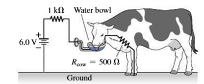
FIGURE 25.43 Stray voltage can bankrupt a dairy farm (Passage Problems 83-86)
83. The current through the 500-Ω cow will be
- a. 3 mA.
- b. 4 mA.
- c. 6 mA.
- d. 12 mA.
84. The voltage across the cow shown is
- a. 2 V.
- b. 4 V.
- c. 6 V.
- d. nearly 0 V.
85. In an effort to diagnose the problem, a farmer connects an ideal voltmeter between the water bowl and ground, with the cow absent. The voltmeter reading is
- a. 2 V.
- b. 4 V.
- c. 6 V.
- d. none of the above.
86. To explore the problem further, a farmer connects an ideal ammeter between the water bowl and ground, with the cow absent. The ammeter reading is
- a. 4 mA.
- b. 6 mA.
- c. 12 mA.
- d. infinite.
Want to see the full answer?
Check out a sample textbook solution
Chapter 25 Solutions
Essential University Physics (3rd Edition)
Additional Science Textbook Solutions
The Cosmic Perspective (8th Edition)
College Physics (10th Edition)
Sears And Zemansky's University Physics With Modern Physics
Physics: Principles with Applications
Physics for Scientists and Engineers: A Strategic Approach, Vol. 1 (Chs 1-21) (4th Edition)


- The circuit shown in Figure P28.78 is set up in the laboratory to measure an unknown capacitance C in series with a resistance R = 10.0 M powered by a battery whose emf is 6.19 V. The data given in the table are the measured voltages across the capacitor as a function of lime, where t = 0 represents the instant at which the switch is thrown to position b. (a) Construct a graph of In (/v) versus I and perform a linear least-squares fit to the data, (b) From the slope of your graph, obtain a value for the time constant of the circuit and a value for the capacitance. v(V) t(s) In (/v) 6.19 0 5.56 4.87 4.93 11.1 4.34 19.4 3.72 30.8 3.09 46.6 2.47 67.3 1.83 102.2arrow_forwardReferring to Figure CQ21.4, describe what happens to the light-bulb after the switch is closed. Assume the capacitor has a large capacitance and is initially uncharged. Also assume the light illuminates when connected directly across the battery terminals.arrow_forwardFigure P18.26 shows a voltage divider, a circuit used to obtain a desired voltage Vout from a source voltage . Determine the required value of R2 if = 5.00 V, Vout = 1.50 V and R1 = 1.00 103 (Hint: Use Kirchhoff's loop rule, substituting Vout = IR2, to find the current. Then solve Ohms law for R2. Figure P18.26arrow_forward
- Figure 21.55 shows how a bleeder resistor is used to discharge a capacitor after an electronic device is shut off allowing a person to work on the electronics with less risk of shock, (a) What is the time constant? (b) How long will it take to reduce the voltage on the capacitor to 0.250% (5% of 5%) of its full value once discharge begins? (c) If the capacitor is charged to a voltage V0through a 100-O resistance, calculate the time it takes to rise to 0.865V0(This is about two time constants.)arrow_forwardFigure P18.26 shows a voltage divider, a circuit used to obtain a desired voltage Vout from a source voltage . Determine the required value of R2 if = 5.00 V, Vout = 1.50 V and R1 = 1.00 103 (Hint: Use Kirchhoff's loop rule, substituting Vout = IR2, to find the current. Then solve Ohms law for R2. Figure P18.26arrow_forwardThe temperature near the center of the Sun is thought to be 15 million degrees Celsius ( 1.5107oC ) (or kelvin). Through what voltage must a singly charged ion be accelerated to have the same energy as the average kinetic energy of ions at this temperature?arrow_forward
- According to its design specification, the timer circuit delaying the closing of an elevator door is to have a capacitance of 32.0 F between two points A and B. When one circuit is being constructed, the inexpensive but durable capacitor installed between these two points is found to have capacitance 34.8 F. To meet the specification, one additional capacitor can be placed between the two points. (a) Should it be in series or in parallel with the 34.8-F capacitor? (b) What should be its capacitance? (c) What If? The next circuit comes down the assembly line with capacitance 29.8 F between A and B. To meet the specification, what additional capacitor should be installed in series or in parallel in that circuit?arrow_forwardThe circuit in Figure P21.59 has been connected for a long time. (a) What is the potential difference across the capacitor? (b) If the battery is disconnected from the circuit, over what time interval does the capacitor discharge to one-tenth its initial voltage?arrow_forwardIntegrated Concepts (a) What energy is dissipated by a lightning bolt having a 20,000-A current, a voltage of 1.00102 MV, and a length of 1.00 ms? (b) What mass of tree sap could be raised from 18.0°C to its boiling point and then evaporated by this energy, assuming sap has the same thermal characteristics as water?arrow_forward
- A charge Q is placed on a capacitor of capacitance C. The capacitor is connected into the circuit shown in Figure P26.37, with an open switch, a resistor, and an initially uncharged capacitor of capacitance 3C. The switch is then closed, and the circuit comes to equilibrium. In terms of Q and C, find (a) the final potential difference between the plates of each capacitor, (b) the charge on each capacitor, and (c) the final energy stored in each capacitor. (d) Find the internal energy appearing in the resistor. Figure P26.37arrow_forwardSuppose you need to measure the potential difference between the points in Figure P29.4. Assume the voltmeter reading is the potential difference between the two leads: V = Vred Vblack. For each of the following measurements, determine at which point you would connect the red lead and at which point you would connect the black lead: a. Vb Va. b. Vc Vb. c. Vd Vc. d. Va Vd. FIGURE P29.4 Problems 4, 5, and 6.arrow_forwardA battery with = 6.00 V and no internal resistance supplies current to the circuit shown in Figure P27.9. When the double-throw switch S is open as shown in the figure, the current in the battery is 1.00 mA. When the switch is closed in position a, the current in the battery is 1.20 mA. When the switch is closed in position b, the current in the battery is 2.00 mA. Find the resistances (a) R1, (b) R2, and (c) R3. Figure P27.9 Problems 9 and 10.arrow_forward
 Physics for Scientists and Engineers, Technology ...PhysicsISBN:9781305116399Author:Raymond A. Serway, John W. JewettPublisher:Cengage Learning
 Principles of Physics: A Calculus-Based TextPhysicsISBN:9781133104261Author:Raymond A. Serway, John W. JewettPublisher:Cengage Learning
 College PhysicsPhysicsISBN:9781938168000Author:Paul Peter Urone, Roger HinrichsPublisher:OpenStax College
 Physics for Scientists and Engineers with Modern ...PhysicsISBN:9781337553292Author:Raymond A. Serway, John W. JewettPublisher:Cengage Learning
 Physics for Scientists and EngineersPhysicsISBN:9781337553278Author:Raymond A. Serway, John W. JewettPublisher:Cengage Learning
 Physics for Scientists and Engineers: Foundations...PhysicsISBN:9781133939146Author:Katz, Debora M.Publisher:Cengage Learning