Physics (5th Edition)
5th Edition
ISBN: 9780321976444
Author: James S. Walker
Publisher: PEARSON
expand_more
expand_more
format_list_bulleted
Videos
Textbook Question
Chapter 24, Problem 84GP
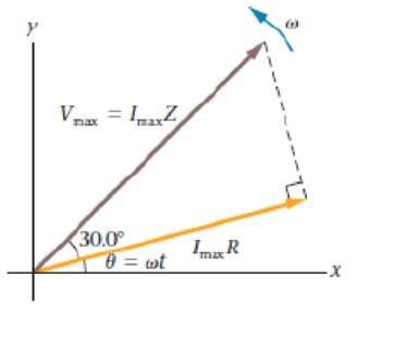
Predict/Calculate Figure 24-39 shows the phasor diagram for an RLC circuit in which the impedance is 337Ω. (a) What is the resistance, R, in this circuit? (b) Is this circuit driven at a frequency that is greater than, less than, or equal to the resonance frequency of the circuit? Explain.
Expert Solution & Answer
Want to see the full answer?
Check out a sample textbook solution
Chapter 24 Solutions
Physics (5th Edition)
Ch. 24.1 - A circuit has a sinusoidally varying current whose...Ch. 24.2 - Circuit 1 has a capacitor with a capacitance C and...Ch. 24.3 - The two circuits shown in Figure 24-14 have...Ch. 24.4 - A circuit consists of an ac generator and an...Ch. 24.5 - Prob. 5EYUCh. 24.6 - An RLC circuit has a resonance frequency of 60 Hz....Ch. 24 - Why is the current in an ac circuit not always in...Ch. 24 - An LC circuit is driven at a frequency higher than...Ch. 24 - An LC circuit is driven at a frequency lower than...Ch. 24 - Prob. 4CQ
Ch. 24 - Prob. 5CQCh. 24 - Two RLC circuits have different values of L and C....Ch. 24 - Can an RLC circuit have the same impedance at two...Ch. 24 - An ac generator produces a peak voltage of 75 V....Ch. 24 - In many European homes the rms voltage available...Ch. 24 - An rms voltage of 120 V produces a maximum current...Ch. 24 - The rms current in an ac circuit with a resistance...Ch. 24 - A 3.33-k resistor is connected to a generator with...Ch. 24 - A 75-watt lightbulb uses an average power of 75 W...Ch. 24 - Inverter Efficiency An array of solar panels...Ch. 24 - Prob. 8PCECh. 24 - The reactance of a capacitor is 65 at a frequency...Ch. 24 - The capacitive reactance of a capacitor at 60 0 Hz...Ch. 24 - A 105-F capacitor is connected to an ac generator...Ch. 24 - The rms voltage across a 0.010-F capacitor is 2.8...Ch. 24 - Predict/Calculate The rms current through a 55.5-F...Ch. 24 - The maximum current in a 22-F capacitor connected...Ch. 24 - PredicCalculate An rms voltage of 20 5 V with a...Ch. 24 - A circuit consists of a 2.00-kHz generator and a...Ch. 24 - A 0.22-F capacitor is connected to an ac generator...Ch. 24 - At what frequency will a generator with an rms...Ch. 24 - PredicCalculate A 22 0-Fcapacitor is connected to...Ch. 24 - Find the impedance of a 60 0-Hz circuit with a...Ch. 24 - An ac generator with a frequency of 125 Hz and an...Ch. 24 - The rms current in an RC circuit is 0.72 A. The...Ch. 24 - When an ac generator with a frequency of 180 Hz...Ch. 24 - A 50 0-Hz generator with an rms voltage of 115 V...Ch. 24 - (a) At what frequency must the circuit in Problem...Ch. 24 - Find the power factor for an RC circuit connected...Ch. 24 - Predict/Calculate (a) Determine the power factor...Ch. 24 - Square-Wave Voltage II The square-wave voltage...Ch. 24 - Prob. 29PCECh. 24 - An inductor has a reactance of 56 5 at 85 0 Hz....Ch. 24 - What is the rms current in a 97 5-mH inductor when...Ch. 24 - What rms voltage is required to produce an rms...Ch. 24 - Loudspeaker Impedance A loudspeakers impedance is...Ch. 24 - Prob. 34PCECh. 24 - A 525- resistor and a 295-mH inductor are...Ch. 24 - The rms current in an RL circuit is 0 26 A when it...Ch. 24 - An ac generator with a frequency of 1 55 kHz and...Ch. 24 - Predict/Calculate An rms voltage of 22 2 V with a...Ch. 24 - A 0.22-H inductor is connected to an ac generator...Ch. 24 - The phase angle in a certain RL circuit is 68 at a...Ch. 24 - (a) Sketch the phasor diagram for an ac circuit...Ch. 24 - A large air conditioner has a resistance of 7 0 ...Ch. 24 - Prob. 43PCECh. 24 - Prob. 44PCECh. 24 - Prob. 45PCECh. 24 - Predict/Explain (a) When the ac generator in...Ch. 24 - Prob. 47PCECh. 24 - Predict/Explain (a) When the ac generator in...Ch. 24 - Find the rms voltage across each element in an RLC...Ch. 24 - What is the impedance of a 1 50-kQ resistor, a...Ch. 24 - Consider the circuit shown in Figure 24-34 The ac...Ch. 24 - What is the phase angle in an RLC circuit with R =...Ch. 24 - An ac voltmeter, which displays the rms voltage...Ch. 24 - Prob. 54PCECh. 24 - (a) Sketch the phasor diagram for an ac circuit...Ch. 24 - A generator connected to an RLC circuit has an rms...Ch. 24 - Prob. 57PCECh. 24 - Predict/Explain In an RLC circuit a second...Ch. 24 - An RLC circuit has a resonance frequency of 1 9...Ch. 24 - The Magnetron A magnetron in a kitchen microwave...Ch. 24 - At resonance, the rms current in an RLC circuit is...Ch. 24 - The resistance in an RLC circuit is doubled (a)...Ch. 24 - Predict/Calculate The capacitive reactance in an...Ch. 24 - Predict/Calculate The capacitive reactance in an...Ch. 24 - A 115- resistor, a 67 6-mH inductor, and a 189-F...Ch. 24 - (a) Find the frequency at which an 18-F capacitor...Ch. 24 - Consider an RLC circuit with R = 105 , L- 518 mH,...Ch. 24 - Predict/Calculate An RLC circuit has a resonance...Ch. 24 - An RLC circuit has a capacitance of 0 29 F. (a)...Ch. 24 - CE BIO Persistence of Vision Although an...Ch. 24 - CE An RLC circuit is driven at its resonance...Ch. 24 - CE Predict/Explain Suppose the circuits shown in...Ch. 24 - Prob. 73GPCh. 24 - Prob. 74GPCh. 24 - A 4 40-F and an 8.80-F capacitor are connected in...Ch. 24 - A 4.40-F and an 8.80-F capacitor are connected in...Ch. 24 - A 12.5-F capacitor and a 47.5-F capacitor are...Ch. 24 - CE A generator drives an RLC circuit with the...Ch. 24 - Trapped on a deserted island, you salvage some...Ch. 24 - Predict/Calculate When a certain resistor is...Ch. 24 - Find the average power consumed by an RC circuit...Ch. 24 - A 1 15-k resistor and a 505-mH inductor are...Ch. 24 - Prob. 83GPCh. 24 - Predict/Calculate Figure 24-39 shows the phasor...Ch. 24 - Prob. 85GPCh. 24 - Predict/Calculate Black-Box Experiment You are...Ch. 24 - An RLC circuit with R = 20.0 , L = 295 mH, and C =...Ch. 24 - A Light-Dimmer Circuit The intensity of a...Ch. 24 - An electric motor with a resistance of 15 arid an...Ch. 24 - Predict/Calculate Tuning a Radio A radio tuning...Ch. 24 - If the maximum voltage in the square wave shown in...Ch. 24 - An ac generator supplies an rms voltage of 5.00 V...Ch. 24 - An RC circuit consists of a resistor R = 32 , a...Ch. 24 - Prob. 94PPCh. 24 - Prob. 95PPCh. 24 - Prob. 96PPCh. 24 - Prob. 97PPCh. 24 - Prob. 98PPCh. 24 - Prob. 99PP
Additional Science Textbook Solutions
Find more solutions based on key concepts
For the coils in the preceding problem, what is the magnetic field at the center of either coil?
University Physics Volume 2
60. You are 9.0 m from the door of your bus, behind the bus, when it pulls away with an acceleration of 1.0 m/...
Physics for Scientists and Engineers: A Strategic Approach with Modern Physics (4th Edition)
TEST YOUR UNDERSTANDING OF SECTION 14.5 When a body oscillating on a horizontal spring passes through its equil...
University Physics with Modern Physics (14th Edition)
64. Which is more polar: a sulfur-bromine (S-Br) bond or a selenium-chlorine (Se-Cl) bond?
Conceptual Physical Science (6th Edition)
3. What is free-fall, and why does it make you weightless? Briefly describe why astronauts are weightless in th...
The Cosmic Perspective (8th Edition)
Knowledge Booster


Learn more about
Need a deep-dive on the concept behind this application? Look no further. Learn more about this topic, physics and related others by exploring similar questions and additional content below.Similar questions
- In a series RLC circuit with a maximum current of 0.250 A, an AC source with Vmax= 115 V operating at 60.0 Hz is connected to a 325-mH inductor, a 7.50-F capacitor, and a resistor with unknown resistance R. Draw a phasor diagram for this circuit, including the current, the potential difference across each of the circuit elements, and the source emf. Draw your diagram with the current phasor pointing upward along the vertical axis.arrow_forwardAn RLC series circuit consists of a 10 resistor, an 8.0F capacitor, and a 50-mH inductor. A 110-V (rms) source of variable frequency is connected across the combination. What is the power output of the source when its frequency is set to one-half the resonant frequency of the circuit?arrow_forwardAn RLC series circuit has a 2.50 (resistor, a 100 (H inductor, and an 80.0 (F capacitor. (a) Find the circuit's impedance at 120 Hz. (b) Find the circuit’s impedance at 5.00 kHz. (c) If the voltage source has Vrms = 5.60 V, what is Irms at each frequency? (d) What is the resonant frequency of the circuit? (e) What is Irms at resonance?arrow_forward
- P33.80a shows a parallel RLC circuit. The instantaneous voltages (and rms voltages) across each of the three circuit elements are the same, and each is in phase with the current in the resistor. The currents in C and L lead or lag the current in the resistor as shown in the current phasor diagram, Figure P33.80b. (a) Show that the rms current delivered by the source is Irms=Vrms[1R2+(C1L)2]12 (b) Show that the phase angle between Vrms and Irms is given by tan=R(1Xc1XL)arrow_forwardAn RLC series circuit hag a 1.00 k(register, a 150 (H inductor, and a 25.0 nF capacitor. (a) Find the circuit’s impedance at 500 Hz. (b) Find the circuit’s impedance at 7.50 kHz. (c) It the voltage source has Vrms = 408 V, what is Irms at each frequency? (d) What is the resonant frequency of the circuit? (e) What is Irms at resonance?arrow_forwardAt 1000 Hz, the reactance of a 5.0-mH inductor is equal to the reactance of a particular capacitor. What is the capacitance of the capacitor?arrow_forward
- A series RLC circuit has resistance R = 50.0 and inductance L. = 0.500 H. (a) Find the circuits capacitance C if the voltage source operates at a frequency of f = 60.0 Hz and the impedance is Z = R = 50.0 . (b) What is the phase angle between the current and the voltage?arrow_forwardA 20-mH inductor is connected across an AC source with a variable frequency and a constant-voltage amplitude of 9.0 V. (a) Determine the reactance of the circuit and the maximum current through the inductor when the frequency Is set at 20 kHz. (b) Do the same calculations for a frequency of 60 Hz.arrow_forwardA series RLC circuit has resistance R = 50.0 and inductance L. = 0.500 H. (a) Find the circuits capacitance C if the voltage source operates at a frequency of f = 60.0 Hz and the impedance is Z = R = 50.0 . (b) What is the phase angle between the current and the voltage?arrow_forward
- A 1.5k resistor and 30-mH inductor are connected in series, as below, across a120-V(rms)ac power source oscillating at 60-Hz frequency. (a) Find the current in the circuit. (b) Find the voltage drops across the resistor and inductor. (C) Find the impedance of the circuit. (d) Find the power dissipated in the resistor. (e) Find the power dissipated in the inductor. (1) Find the power produced by the source.arrow_forwardAn AC generator with an rms emf of 15.0 V is connected in series with a 0.54-H inductor. The frequency of the source emf is 70.0 Hz. Draw a phasor diagram for this circuit, including the current, the potential difference across the inductor, and the source emf. Draw your diagram with the current phasor pointing toward the right along the horizontal axis.arrow_forwardReview. The voltage phasor diagram for a certain series RLC circuit is shown in Figure P33.59. The resistance of the circuit is 75.0 , and the frequency is 60.0 Hz. Find (a) the maximum voltage Vmax, (b) the phase angle , (c) the maximum current, (d) the impedance, (e) the capacitance and (f) the inductance of the circuit, and (g) the average power delivered to the circuit.arrow_forward
arrow_back_ios
SEE MORE QUESTIONS
arrow_forward_ios
Recommended textbooks for you
 College PhysicsPhysicsISBN:9781938168000Author:Paul Peter Urone, Roger HinrichsPublisher:OpenStax College
 Physics for Scientists and Engineers: Foundations...PhysicsISBN:9781133939146Author:Katz, Debora M.Publisher:Cengage Learning
 Physics for Scientists and Engineers, Technology ...PhysicsISBN:9781305116399Author:Raymond A. Serway, John W. JewettPublisher:Cengage Learning
 College PhysicsPhysicsISBN:9781305952300Author:Raymond A. Serway, Chris VuillePublisher:Cengage Learning
 College PhysicsPhysicsISBN:9781285737027Author:Raymond A. Serway, Chris VuillePublisher:Cengage Learning
College Physics
Physics
ISBN:9781938168000
Author:Paul Peter Urone, Roger Hinrichs
Publisher:OpenStax College
Physics for Scientists and Engineers: Foundations...
Physics
ISBN:9781133939146
Author:Katz, Debora M.
Publisher:Cengage Learning
Physics for Scientists and Engineers, Technology ...
Physics
ISBN:9781305116399
Author:Raymond A. Serway, John W. Jewett
Publisher:Cengage Learning
College Physics
Physics
ISBN:9781305952300
Author:Raymond A. Serway, Chris Vuille
Publisher:Cengage Learning
College Physics
Physics
ISBN:9781285737027
Author:Raymond A. Serway, Chris Vuille
Publisher:Cengage Learning
Introduction To Alternating Current; Author: Tutorials Point (India) Ltd;https://www.youtube.com/watch?v=0m142qAZZpE;License: Standard YouTube License, CC-BY