
Videos
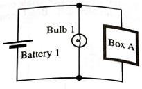
In the circuit at right, the voltage across bulb 1 and the voltage across box A are equal. What, if anything, can you say about the resistance of box A compared to the resistance of bulb 1? Explain.
Write an expression for the voltage across the battery

Learn your wayIncludes step-by-step video

Chapter 20 Solutions
Tutorials in Introductory Physics
Additional Science Textbook Solutions
College Physics (10th Edition)
University Physics (14th Edition)
Essential University Physics: Volume 1 (3rd Edition)
An Introduction to Thermal Physics
College Physics
Essential University Physics (3rd Edition)


- A circuit contains a source of constant voltage V and two resistors connected in parallel, as shown in (Figure 1). Resistor 1 has resistance R1, and resistor 2 has resistance R2. Part C Now consider three resistors in parallel, with resistances R1, R2, and R3, as shown in (Figure 3). Again, draw a circuit diagram with a single equivalent resistor, with resistance R. What is the value of R? Figure 1 of 3 Express your answer in terms of R1, R2, and R3. V ΑΣΦ ? V R1 R2 R =arrow_forwardApplying Kirchoff's Rules If in the circuit shown, V1 = 4V, V2 = 12V, R1 = 3 Ohms, R2 = 1 Ohm, and R3 = 3 Ohms, the current I₁ is amps, the current I2 is amps, the current I3 is decimal point.) + V1 R2 amps. (Provide answer with one digit to the right of the R3 I2 13 R1 www V2 +arrow_forwardIn the circuit below, if the battery in the circuit below is 3V, resistor R1=2772, and resistor R2=4122, what is the total or net current in the circuit units of mA? High potential I R1 R2 + 12 I Low potential Note: It is understood that the unit of your answer is in milli-Amps (mA), however do not explicitly include units in your answer. Enter only a number. If you do enter a unit, your answer will be counted wrong.arrow_forward
- Consider the circuit shown in the figure. Take R,=R, R2=2R and R3=R. Find the magnitude of the current passing through the resistor R, in terms of V/R. Express your answer using one decimal place. 3V R1 4V R2 R3arrow_forwardWhere V is the voltage in volts (symbol V), I is the current in amperes or amps (symbol A), and R is the resistance in ohms (symbol 2). So the following simple circuit shows a battery and a resistor R: R www Hiltarrow_forwardConsider the circuit in (Figure 1). Suppose that v₁ = 14 V, v2 = 5 V, and i = 5 mA. Figure i + 1 of 1 5 mA source is absorbing power. 5 V and 14 V sources are developing power. 5 V and 14 V sources are absorbing power. 5 mA source is developing power. All sources are absorbing power. O All sources are developing power. Submit Correct Part G Previous Answers What is the total power developed in the circuit if the polarity of the 14 V source is reversed? Express your answer to three significant figures and include the appropriate units. P= 25 Submit mW Previous Answers Request Answer ? X Incorrect; Try Again; 3 attempts remainingarrow_forward
- In the circuit in (Figure 1) the voltage and current expressions are v = 36e 25t V, t≥ 0; i = 12e 25 mA, Figure C t≥0¹. + VR T 1 of 1 Part A Find R. Express your answer to three significant figures and include the appropriate units. ► View Available Hint(s) R = Submit Part B μÅ Value Units ? Find C. Express your answer to three significant figures and include the appropriate units. ► View Available Hint(s)arrow_forwardPart a: what is the equivalent capacitance of the circuit shown above? Give your answer in microfarads. part b: what is the charge on the 4.0 mu*F capacity? Give your answer in microcoulombs par t c:What is the voltage on the 4mu*F capacitor ? Give your answer in Volts part c What is the voltage on the 2.0uF capacitor? Give your answer in Volts part d :arrow_forwardA 24.0 V battery is wired in parallel with three resistors, R1 = 10.0 Ohms, R2 = 60.0 Ohms, and R3 = 150.0 Ohms. a.) Using either the computer drawing tools or a scanned hand written diagram, draw this circuit including proper symbols and labels. (Do not copy and paste an image from any other resource) b.) Find the equivalent resistance and total current running through the circuit. Show your work and label the current flow on your diagram. c.) Find the current flow and voltage drop through each resistor. Show your work and explain.arrow_forward
- Consider the following electrical circuit ... R1 R3 R2 The current through the circuit (in amps) is determined by the voltage through the circuit (in volts) divided by the resistance (in ohms) through the circuit. Complete the script to calculate the total current through the circuit This is the script for calculating the total current of the circuit R1 = 5; R2 = 10; R3 = 2; V = 6; RI = 1/( (1/Blank 1)+(1/Blank 2)) +Blank 3 I = Blank 4/Blank 5 Blank 1 Add your answer Blank 2 Add your answer Blank 3 Add your answer Blank 4 Add your answer Blank 5 Add your answerarrow_forwardThe combined electrical resistance R of two resistors R, and R. connected in parallel, is given by the equation below, where R, R₁, and are measured in ohms. R₁ and R, are increasing at rates of 0.5 and 2.0 ohms per second, respectively. 1 1 1 R₁+R₂ At what rate is R changing when R, 32 ohms and R₂ = 75 ohms? (Round your answer to three decimal places.) 0.573 xohm/sec Need Help? Read Watch Itarrow_forwardFor the circuit shown in the figure below, determine voltages (voltage drops) Vị, V2 , absolute voltage Va at node a versus ground, and circuit current I. Express voltages in volts and current in milliamperes. Keep three significant digits. You are given Vs = 10 V. + + V, - 8 kO a + 14 4 kΩ. V2 Vs 4 ΚΩΣ OV -arrow_forward
 University Physics Volume 1PhysicsISBN:9781938168277Author:William Moebs, Samuel J. Ling, Jeff SannyPublisher:OpenStax - Rice University