
Concept explainers
Videos
For a specific application, the circuit shown in Fig. 2.140 was designed so that IL = 83.33 mA and that Rin = 5 kΩ. What are the values of R1 and R2?
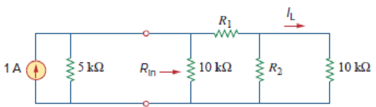
Figure 2.140
Calculate the values of
Answer to Problem 81CP
The values of
Explanation of Solution
Given Data:
Refer to Figure 2.140 in the textbook for the given circuit.
Formula used:
Consider the expression for
Here,
Consider the expression for
Calculation:
Modify Figure 2.140 as shown in Figure 1.
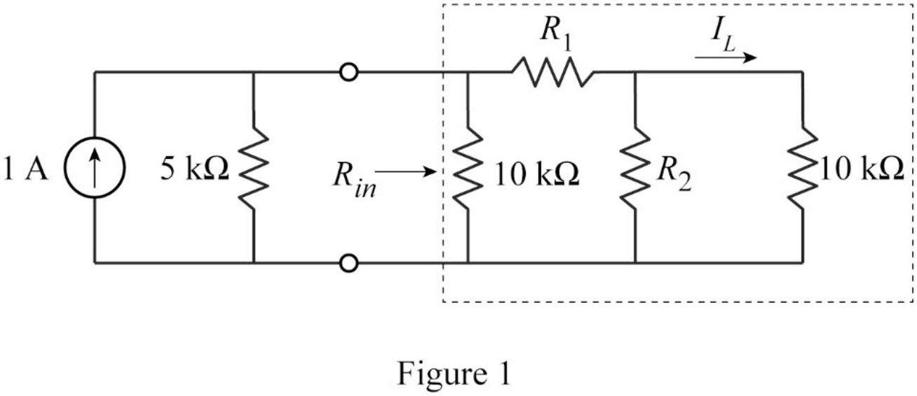
In Figure 1,
Therefore,
From Figure 1, write the expression for equivalent resistance
Substitute
To maintain
Modify the Figure as shown in Figure 2.
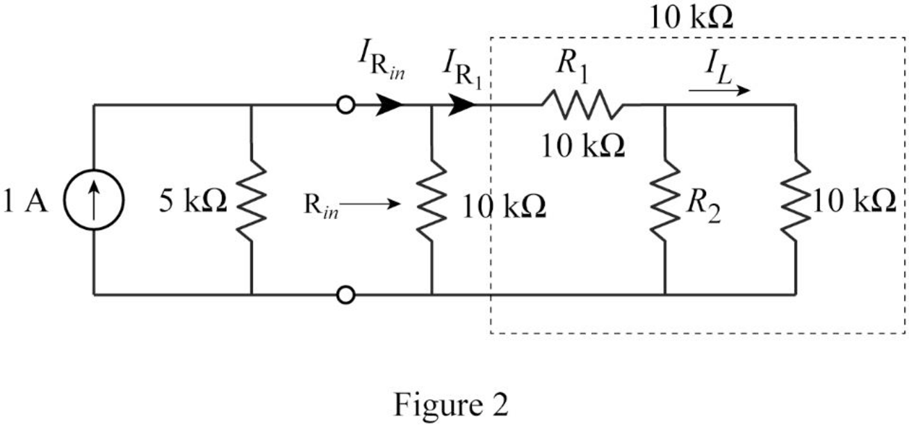
Therefore from current division rule, the current through
From current division rule, write the expression for current
Substitute
Rearrange the equation as follows.
Simplify the equation as follows.
Simplify the equation as follows.
Substitute
Simplify the equation as follows.
Simplify the equation to obtain the value of
Conclusion:
Thus, the values of
Want to see more full solutions like this?
Chapter 2 Solutions
Fundamentals of Electric Circuits


- 19) Irv- 40 V and the battery is ideal, what is the potential difference across Ri in the figuret R,- 100 A) 6.7 V B) 8.0 V C) 10 V D) 20 V V. R,- 20 1 20 0 R- 30 narrow_forward3.1 Find the equivalent resistance Rab for each of the circuits in the following figure. a b 5052 9052 {30012 802 $10052 $7052arrow_forwardThe total resistance of the circuit shown in Figure 12 below is to 1MO 560kO 5.6 MO 10 MO Figure 12 A 1256 6 kO 17.84 MQ C 1256 6 MO D. 16600 k O A B.arrow_forward
- Consider the given circuit, where is = 3e-tmA. The current i2(t)=2.06 e-t mA. What is L in H? 4 mH 6 mH eq all allarrow_forwardQ-1. Analyze the circuit in Figure 1 to find its output. Q2 T Q T Q T Q Clock Q Figure Iarrow_forwardFor the circuit in Figure 3: a) Find Ipo, VGsa and Vp. b) Plot the Q point. 9 22 V 2.2 ΚΩ Ipe VGSTH) = 3 V IDon) = 5 mA VGS(on) = 6 V 1 M2 VpsQ 0.75 k2 Figure 3arrow_forward
- Listen R₁ *: 22 ΚΩ Vino (a) R₁ ww 150 kQ D out (b) OV out The circuit or circuits with a virtual ground is (c) and (d) (a) (b) (d) all figures represent circuits with virtual ground V out R₁ {82 ΚΩ wwwww R₁ 10 ΚΩ (d) wwwwww OV 343 Rf 33ΚΩ RN out {R₁ 2.7 ΚΩarrow_forwardA 4.5MF Copacitor to a 74 K A Arilo ohms resistor with ç=20ov. initially unchucged is connected and an emf sourse 1) current in th Ac Circvit immediatlu of ter Saritch s clored?: b)cuirentin Ke ciccuit AMor vera long time after Switch s closed> ) what is te Charge On the copurilor ofter a verq long time atter the Sw/tch s i's clordi 1 How long After the Smitch is Closed (cached 50%0 has the coporitm of idy Pinal voltage.arrow_forwardCircuits IShow you solution pleasearrow_forward
- Find the Leq. Between points A and B in figure (3). L. L=2mM Li=4mH LI LI L A 四arrow_forwardFind the DC base current of Q1 (i.e. Ig1) for the following circuit. VBE = 0.7 V (B1 = 64, B2 = 120) %D 010V Q2 Vị 1k 5V 502arrow_forwardDetermine the voltage V1 in Volts for the following circuit with component values ISRC = 1.5 mA, VSRC = 7 V, R1 = 2.2 kQ, R2 = 3.4 k2, and R3 = 1.0 kQ. 11 Vsrc Isrc + V1 + R1 m R2 R3 m 12 13arrow_forward
 Introductory Circuit Analysis (13th Edition)Electrical EngineeringISBN:9780133923605Author:Robert L. BoylestadPublisher:PEARSON
 Delmar's Standard Textbook Of ElectricityElectrical EngineeringISBN:9781337900348Author:Stephen L. HermanPublisher:Cengage Learning
 Programmable Logic ControllersElectrical EngineeringISBN:9780073373843Author:Frank D. PetruzellaPublisher:McGraw-Hill Education
 Fundamentals of Electric CircuitsElectrical EngineeringISBN:9780078028229Author:Charles K Alexander, Matthew SadikuPublisher:McGraw-Hill Education
 Electric Circuits. (11th Edition)Electrical EngineeringISBN:9780134746968Author:James W. Nilsson, Susan RiedelPublisher:PEARSON
 Engineering ElectromagneticsElectrical EngineeringISBN:9780078028151Author:Hayt, William H. (william Hart), Jr, BUCK, John A.Publisher:Mcgraw-hill Education,