
International Edition---engineering Mechanics: Statics, 4th Edition
4th Edition
ISBN: 9781305501607
Author: Andrew Pytel And Jaan Kiusalaas
Publisher: CENGAGE L
expand_more
expand_more
format_list_bulleted
Concept explainers
Videos
Textbook Question
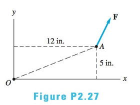
Chapter 2, Problem 2.27P
Determine the moment of the force
Expert Solution & Answer

Trending nowThis is a popular solution!

Students have asked these similar questions
The bucket of the excavator at a construction site is subjected to F = 1530 lb and F, = 790 lb digging forces at its tip. Determine the magnitude and direction of their resultant. Use the vector algebra and vector polygon methods. Compare the answers with the two methods to verify the
accuracy of your work.
(Express your answers using four and three significant figures, respectively. Report the direction as an angle between 0 and 180°, clockwise or counterclockwise.)
R =
lb
v from i
Select
Five forces and a couple act on the plate shown in the figure .
- Find the resultant ( R ) Of the four forces , and its angle (e).
- Locate it with respect to point ( O).
- Show where the resultant cuts both the x - and y- axes.
400KN
7m
1o0 KN
6 m
lom
800 KN-m
V150 KN
18m
7200KN
100 KN
L 8 m
Given: F1={9 i - 9 j+ 10 k}lb F2={-10 i+10 j+ 10 k}lb Find: the Magnitude of the Resultant moment in (Ib.ft) generated by the forces about point
O.
4 ft
5 ft
3 ft
Chapter 2 Solutions
International Edition---engineering Mechanics: Statics, 4th Edition
Ch. 2 - Â Which of the force system shown are equivalent...Ch. 2 - Two men are trying to roll the boulder by applying...Ch. 2 - The magnitudes of the three forces applied to the...Ch. 2 - Replace the three forces by a single equivalent...Ch. 2 - Replace the three forces with a single equivalent...Ch. 2 - The forces P1=110lb,P2=200lb, and P3=150lb are...Ch. 2 - Determine the magnitudes of the three forces...Ch. 2 - The magnitudes of the three forces acting on the...Ch. 2 - Determine the three forces acting on the plate...Ch. 2 - The force R is the resultant of the forces P1,P2,...
Ch. 2 - Knowing that the resultant of the two forces is...Ch. 2 - Knowing that the forces P and Q are equivalent to...Ch. 2 - Three ropes support the weight at A. The tension...Ch. 2 - Find the forces Q1,Q2, and Q3 so that the two...Ch. 2 - The man exerts a force P of magnitude 40 1b on the...Ch. 2 - The three forces acting on the beam can be...Ch. 2 - The trapdoor is held in the horizontal plane by...Ch. 2 - Replace the three forces acting on the guy wires...Ch. 2 - The horizontal boom carries the weight W=108lb at...Ch. 2 - The three forces, each of magnitude F, are applied...Ch. 2 - Determine the resultant force R that is equivalent...Ch. 2 - Determine the magnitude and sense of the moment of...Ch. 2 - Find the magnitude and sense of the moment of the...Ch. 2 - Two forces of magnitude P each act on the beam....Ch. 2 - A force P in the xy-plane acts on the triangular...Ch. 2 - A force P in the xy-plane acts on the triangular...Ch. 2 - Determine the moment of the force F=9i+18jlb about...Ch. 2 - Given that T=43kN and W=38kN, determine the...Ch. 2 - A moment of 50lbft about O is required to loosen...Ch. 2 - Determine the moment of the force F about point A...Ch. 2 - The resultant of the two forces shown has a line...Ch. 2 - The tow truck's front wheels will be lifted off...Ch. 2 - The force F acts on the gripper of the robot arm....Ch. 2 - Given that the magnitude of the moment of P about...Ch. 2 - The magnitude of the force P is 160 N. Determine...Ch. 2 - The magnitude of the force Q Determine the moments...Ch. 2 - The magnitude of the moment of force P about point...Ch. 2 - The magnitude of the force P is 50 kN. Determine...Ch. 2 - Determine the combined moment of the two forces...Ch. 2 - Find the combined moment of the forces P and Q...Ch. 2 - The wrench is used to tighten a nut on the wheel....Ch. 2 - The magnitudes of the two forces shown are P=16lb...Ch. 2 - The moment of the force F=50i100j70klb about point...Ch. 2 - Determine the magnitude of the moment of the 150-N...Ch. 2 - The combined moment of the two forces, each of...Ch. 2 - The force F=2i12j+5klb acts along the line AB....Ch. 2 - Calculate the combined moment of the three forces...Ch. 2 - Determine the moment of the force F=40i+30j+20kkN...Ch. 2 - Determine the moment of the 400-lb force about...Ch. 2 - The magnitude of the force F is 55 lb. Calculate...Ch. 2 - The force F=18i12j+10kN is applied to the gripper...Ch. 2 - The legs of the tripod have equal lengths. The...Ch. 2 - Determine the moment of the force F=40i8j+5kN...Ch. 2 - To lift the table without tilting, the combined...Ch. 2 - The combined moment of the three forces is zero...Ch. 2 - The trap door is held open by the rope AB. If the...Ch. 2 - The forces P and Q act on the handles of the...Ch. 2 - The magnitude of the force P is 360 N. Determine...Ch. 2 - The combined moment of P and the 20-lb force about...Ch. 2 - Determine the magnitude of the force F given that...Ch. 2 - The force F of magnitude 200Â NÂ isÂ...Ch. 2 - Calculate the moment of the force P about the axis...Ch. 2 - The force systems in Figs. (a) and (b) have the...Ch. 2 - The force F=F(0.6i+0.8j)kN is applied to the frame...Ch. 2 - Determine the combined moment of the four forces...Ch. 2 - The flexible shaft AB of the wrench is bent into a...Ch. 2 - The magnitude of the force F is 180 lb. Find the...Ch. 2 - Which of the systems are equivalent to the couple...Ch. 2 - Which of the systems are equivalent to the couple...Ch. 2 - If the couple applied to the steering wheel is to...Ch. 2 - Determine the magnitude of the couple shown.Ch. 2 - Determine the couple-vector that is equivalent to...Ch. 2 - Calculate the combined moment of the couple C and...Ch. 2 - Determine the couple-vector that is equivalent to...Ch. 2 - The two forces of magnitude F=30kN form a couple....Ch. 2 - The couple acts on the handles of a steering...Ch. 2 - The force system acting on the plate is equivalent...Ch. 2 - A couple of magnitude 3601b ft is applied about...Ch. 2 - The arm ABCD of the industrial robot lies in a...Ch. 2 - The figure shows one-half of a universal coupling...Ch. 2 - The steering column of the rack-and-pinion...Ch. 2 - Which of the systems are equivalent to the...Ch. 2 - A 15-lb force acts at point A on the high-pressure...Ch. 2 - The bracket, which is fastened to a wall by anchor...Ch. 2 - Replace the three forces applied to the beam by an...Ch. 2 - Replace the two forces shown by a force-couple...Ch. 2 - The figure shows a schematic of a torsion-bar...Ch. 2 - Replace the 250-N force with an equivalent...Ch. 2 - The magnitude of the force F acting at point A on...Ch. 2 - Replace the force-couple system acting on the pipe...Ch. 2 - (a) Replace the force F=2800i+1600j+3000klb acting...Ch. 2 - Determine the force-couple system, with the force...Ch. 2 - Replace the force F and the couple C with an...Ch. 2 - The moment of the force P about the axis AB is...Ch. 2 - Replace the force and the couple shown with an...Ch. 2 - The tensions in the cables supporting the pole are...Ch. 2 - The force acting at A is F=10i+20j5kkN. Knowing...Ch. 2 - The magnitude of the moment of the force P about...Ch. 2 - Calculate the couple-vector formed by the two...Ch. 2 - The magnitudes of the force P and couple C are...Ch. 2 - The resultant force of the three cable tensions...Ch. 2 - The force-couple system shown is equivalent to the...Ch. 2 - Replace the two forces shown with an equivalent...Ch. 2 - The three forces of magnitude P can be replaced by...Ch. 2 - Knowing that the two forces shown can be replaced...Ch. 2 - The trapdoor is held in the position shown by two...Ch. 2 - The force system consists of the force...Ch. 2 - The force system shown can be replaced with a...
Knowledge Booster


Learn more about
Need a deep-dive on the concept behind this application? Look no further. Learn more about this topic, mechanical-engineering and related others by exploring similar questions and additional content below.Similar questions
- Use Force Distance method to find the moment of each force shown about x, y, and z axes. Then find total moment of all forces about point 0. Draw vector representation of this moment. Question 4: 500 mm. 500 N A 500 mm. 500 mm B 450 N 550 N 250 N C 500 mm 350-Narrow_forwardFind the resultant force vector,R, of the three vectors A,B, and C (i.e., add the vectors), if the magnitude of vector A is 10N, the magnitude of vector B is 17N, and the magnitude of vector C is 9N. Your answer should be in the form R = Rx i+ Ry j, where you determine Rx and Ry, and where i, and j are the unit vectors along the x, and y axis, respectively. YA В A 60° 45°arrow_forwardCan I have the method in vector mathematics. In lifting a heavy box, a man uses a block and tackle attached to the bottom of an I beam at hook B. The man applies 195 N force to end A of the rope. Given: X1 : 2.943 m Z1 : 1.655 m Z2 : 4.167 m a.) Determine the value of Y1 if the z-component of the moment at the origin is 254.558 N·m b.) Determine the x-component pf the Force Vector F. c.) Determine the mass of the box. If you believe that there is no possible way to solve the problem, justify on why the problem is invalid.arrow_forward
- The moment of the force F-480-lb about the point O in Cartesian vector form is. 1 ft> B 4 ft 2 ft 4 ft Select one: O a. Mo = 800;- 1600k O b. Mo = -200j + 400k Oc. Mo =-200j- 400k Od. Mo 200j + 400k EN Garrow_forwardUsing the component method, find the complete resultant of the following forces: F= 2m, 40° N of E, and G = 4m at 127° counterclockwise from East?arrow_forwardPLEASE HELP ME ASAP :( The structure is supported with cables as shown in Figure 3. All dimensions are in meters. a) If T2= 619 N, solve for F and the remaining cables that can hold the allowable force F acting upward at point A to maintain its equilibrium. b) Solve for the magnitude and direction angles of the resultant force for the three cables if T1= 889 N, T2= 1417 N, T3= 1500 N c) Determine the moment of the resultant force about the axis BC.arrow_forward
- A bent tube is attached to a wall with brackets as shown. A force of F = 480 lb is applied to the end of the tube with direction indicated by the dimensions in the figure. a.) Determine the moment about point D due to the force F. Enter your answer in Cartesian components with units of ft-lbs. b.) Determine the moment about a line (i.e. axis) running from D to C due to the force F. Enter your answer in Cartesian components with units of ft-lbs. 2013 Michael Swanbom BY NC SA A FK Values for dimensions on the figure are given in the table below. Note the figure may not be to scale. Be sure to align your cartesian unit vectors with the coordinate axes shown in the figure. Variable Value a 11.4 in 19.4 in 16.5 in d 52.8 in h 37.4 in 44.0 in a. Mp = k) ft-lb b. MpC i + k) ft-lbarrow_forwardc. Find the moment of the forces about point A. d. Find the shortest distance 30 800 N between the lines of action of the two forces. 200 mm G00 mm 30 20 800 Narrow_forwardSolve for the resultant forces and moments at points A and B in diagram belowarrow_forward
- Find the resultant of the following concurrent forces graphically and analytically: FI=100N 37° counterclockwise from the +x-axis F2-100N 50° clockwise from the -x-axis F3-80 N 233° counterclockwise from the +x-axisarrow_forwardDetermine the magnitude and direction of the resultant of the following forces: 50 N at 50 degrees,60 N at 120 degrees,40 N at 220 degrees,30 N at 330 degrees. All angles are measure from the positive x-axis. Use the component method. Select one: a. 75 N: 42º b. 50 N: 87º c. 54 N: 87º d. 101 N: 89ºarrow_forwardGiven the Position vector Ř = i+j+3k (m) and the Force vector F = i - 7j + 2k (kN Determine the angle in degrees between the two vectors. Answer:arrow_forward
arrow_back_ios
SEE MORE QUESTIONS
arrow_forward_ios
Recommended textbooks for you
 International Edition---engineering Mechanics: St...Mechanical EngineeringISBN:9781305501607Author:Andrew Pytel And Jaan KiusalaasPublisher:CENGAGE L
International Edition---engineering Mechanics: St...
Mechanical Engineering
ISBN:9781305501607
Author:Andrew Pytel And Jaan Kiusalaas
Publisher:CENGAGE L
Introduction To Engg Mechanics - Newton's Laws of motion - Kinetics - Kinematics; Author: EzEd Channel;https://www.youtube.com/watch?v=ksmsp9OzAsI;License: Standard YouTube License, CC-BY