
Fundamentals of Electric Circuits
6th Edition
ISBN: 9780078028229
Author: Charles K Alexander, Matthew Sadiku
Publisher: McGraw-Hill Education
expand_more
expand_more
format_list_bulleted
Videos
Textbook Question
Chapter 16.3, Problem 6PP
The initial energy in the circuit of Fig. 16.17 is zero at t = 0. Assume that vs = 360u(t) V. (a) Find Vo(s) using the Thevenin theorem. (b) Apply the initial- and final-value theorems to find vo(0) and vo(∞). (c) Obtain vo(t).
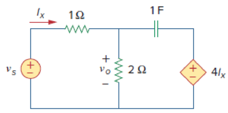
Figure 16.17
Expert Solution & Answer

Trending nowThis is a popular solution!

Students have asked these similar questions
X
R
For the RL circuit, find the mathematical model (input-output relationship) if the output is the inductor voltage, V₁(t)=y(t) and R=17 Q2, L=5 H.
(Watch out for the derivative symbol!)
+
X
R
For the RL circuit, find the mathematical model (input-output relationship) if the output is the resistor voltage, VŔ(t)=y(t) and R=9 02, L=14 H.
(Watch out for the derivative symbol!)
O a. x(t) = y(t) + 1,56y'(t)
O b. x(t) = y(t) + 1,56y(t)
O
c. x(t) = y(t) + 1,56y(t)
O d. x(t) = y(t)+ 0,64y'(t)
O e. x' (t) = y'(t) + 0,64y(t)
O f. x'(t) = y'(t) + 0,64y'(t)
O g. x'(t) = y(t) + 0,64y(t)
Oh. x'(t) = y'(t) + 1,56y(t)
16.30 Find v(t), for all t > 0, in the circuit of Fig. 16.53.
+
7u(t) V (+
) 3.5u(t) A
1H
0.5 F
Chapter 16 Solutions
Fundamentals of Electric Circuits
Ch. 16.2 - Determine vo(t) in the circuit of Fig. 16.6,...Ch. 16.2 - Prob. 2PPCh. 16.2 - Prob. 3PPCh. 16.3 - For the circuit shown in Fig. 16.12 with the same...Ch. 16.3 - Prob. 5PPCh. 16.3 - The initial energy in the circuit of Fig. 16.17 is...Ch. 16.4 - Prob. 7PPCh. 16.4 - Prob. 8PPCh. 16.4 - Prob. 9PPCh. 16.5 - Obtain the state variable model for the circuit...
Ch. 16.5 - Prob. 11PPCh. 16.5 - Prob. 12PPCh. 16.6 - For what value of is the circuit in Fig. 16.29...Ch. 16.6 - Prob. 14PPCh. 16.6 - Prob. 15PPCh. 16.6 - Synthesize the function Vo(s)Vin=2ss2+6s+10 using...Ch. 16 - Prob. 1RQCh. 16 - The current through an RL series circuit with...Ch. 16 - Prob. 3RQCh. 16 - Prob. 4RQCh. 16 - Prob. 5RQCh. 16 - Prob. 6RQCh. 16 - Prob. 7RQCh. 16 - Prob. 8RQCh. 16 - Prob. 9RQCh. 16 - Prob. 10RQCh. 16 - The current in an RLC circuit is described by...Ch. 16 - The differential equation that describes the...Ch. 16 - Prob. 3PCh. 16 - If R = 20 , L = 0.6 H, what value of C will make...Ch. 16 - The responses of a series RLC circuit are vc(t) =...Ch. 16 - Prob. 6PCh. 16 - Prob. 7PCh. 16 - Prob. 8PCh. 16 - Prob. 9PCh. 16 - The step responses of a series RLC circuit are Vc...Ch. 16 - The step response of a parallel RLC circuit is v =...Ch. 16 - Prob. 12PCh. 16 - Prob. 13PCh. 16 - Prob. 14PCh. 16 - For the circuit in Fig. 16.38. calculate the value...Ch. 16 - The capacitor in the circuit of Fig. 16.39 is...Ch. 16 - If is(t) = 7.5e2t u(t) A in the circuit shown in...Ch. 16 - Find v(t), t 0 in the circuit of Fig. 16.41. Let...Ch. 16 - The switch in Fig. 16.42 moves from position A to...Ch. 16 - Find i(t) for t 0 in the circuit of Fig. 16.43.Ch. 16 - In the circuit of Fig. 16.44, the switch moves...Ch. 16 - Find the voltage across the capacitor as a...Ch. 16 - Obtain v (t) for t 0 in the circuit of Fig....Ch. 16 - The switch in the circuit of Fig. 16.47 has been...Ch. 16 - Calculate v(t) for t 0 in the circuit of Fig....Ch. 16 - Prob. 26PCh. 16 - Find v (t) for t 0 in the circuit in Fig. 16.50.Ch. 16 - For the circuit in Fig. 16.51, find v(t) for t 0.Ch. 16 - Prob. 29PCh. 16 - Find vo(t), for all t 0, in the circuit of Fig....Ch. 16 - Prob. 31PCh. 16 - For the network in Fig. 16.55, solve for i(t) for...Ch. 16 - Using Fig. 16.56, design a problem to help other...Ch. 16 - Prob. 34PCh. 16 - Prob. 35PCh. 16 - Prob. 36PCh. 16 - Prob. 37PCh. 16 - The switch in the circuit of Fig. 16.61 is moved...Ch. 16 - Prob. 39PCh. 16 - Prob. 40PCh. 16 - Prob. 41PCh. 16 - Prob. 42PCh. 16 - Prob. 43PCh. 16 - Prob. 44PCh. 16 - Find v(t) for t 0 in the circuit in Fig. 16.68.Ch. 16 - Prob. 46PCh. 16 - Determine io(t) in the network shown in Fig....Ch. 16 - Prob. 48PCh. 16 - Find i0(t) for t 0 in the circuit in Fig. 16.72....Ch. 16 - Prob. 50PCh. 16 - In the circuit of Fig. 16.74, find i(t) for t 0.Ch. 16 - Prob. 52PCh. 16 - In the circuit of Fig. 16.76, the switch has been...Ch. 16 - Prob. 54PCh. 16 - Prob. 55PCh. 16 - Calculate io(t) for t 0 in the network of Fig....Ch. 16 - Prob. 57PCh. 16 - Prob. 58PCh. 16 - Find vo(t) in the circuit of Fig. 16.82 if vx(0) =...Ch. 16 - Prob. 60PCh. 16 - Prob. 61PCh. 16 - Using Fig. 16.85, design a problem to help other...Ch. 16 - Consider the parallel RLC circuit of Fig. 16.86....Ch. 16 - The switch in Fig. 16.87 moves from position 1 to...Ch. 16 - For the RLC circuit shown in Fig. 16.88, find the...Ch. 16 - For the op amp circuit in Fig. 16.89, find v0(t)...Ch. 16 - Given the op amp circuit in Fig. 16.90, if v1(0+)...Ch. 16 - Prob. 68PCh. 16 - Prob. 69PCh. 16 - Using Fig. 16.93, design a problem to help other...Ch. 16 - Prob. 71PCh. 16 - The transfer function of a system is H(s)=s23s+1...Ch. 16 - Prob. 73PCh. 16 - Design a problem to help other students better...Ch. 16 - Prob. 75PCh. 16 - For the circuit in Fig. 16.95, find H(s) =...Ch. 16 - Obtain the transfer function H(s) = VoVs for the...Ch. 16 - Prob. 78PCh. 16 - For the circuit in Fig. 16.97, find: (a) I1/Vs (b)...Ch. 16 - Refer to the network in Fig. 16.98. Find the...Ch. 16 - Prob. 81PCh. 16 - Prob. 82PCh. 16 - Refer to the RL circuit in Fig. 16.101. Find: (a)...Ch. 16 - A parallel RL circuit has R = 4 and L = 1 H. The...Ch. 16 - Prob. 85PCh. 16 - Prob. 86PCh. 16 - Prob. 87PCh. 16 - Prob. 88PCh. 16 - Develop the state equations for the circuit shown...Ch. 16 - Prob. 90PCh. 16 - Prob. 91PCh. 16 - Prob. 92PCh. 16 - Prob. 93PCh. 16 - Prob. 94PCh. 16 - Prob. 95PCh. 16 - Prob. 96PCh. 16 - A system is formed by cascading two systems as...Ch. 16 - Determine whether the op amp circuit in Fig....Ch. 16 - It is desired realize the transfer function...Ch. 16 - Prob. 100PCh. 16 - Prob. 101PCh. 16 - Synthesize the transfer function...Ch. 16 - Prob. 103CPCh. 16 - Prob. 104CPCh. 16 - Prob. 105CP
Knowledge Booster


Learn more about
Need a deep-dive on the concept behind this application? Look no further. Learn more about this topic, electrical-engineering and related others by exploring similar questions and additional content below.Similar questions
- The minimum sum-of- products for the following function isF(A,B,C,D,E)=[m(0,1,15,16,17 ) +[d(14,24,25,30,31) using Quine - McClusky methodarrow_forwardChapter 16, Solution 7. The circuit in the s-domain is shown below. Please note, iL(0) = 0 and v.(0) = o because both sources were equal to zero for all t<0. 2/s At node 1 2/s-V₁ V₁ V₁-V + S m 2/s Vo ²-1 (2+1/s)-V₂ 1/s (1)arrow_forwardx[n]= {3, 0, 0, 0, 3}arrow_forward
- State Diagram Analysis 0/0 1/1 00 01 0/1 1) Create the state table 2) 2) Find A((t+1), B(t+1) and Y(t_ 3) Draw the circuit 0/1 0/1 1/0 10 1/0 1/1 11arrow_forwardProblem 16.024 - Current through inductor The switch in the given circuit has been closed for a long time but is opened at t= 0. Determine (t) for t> 0. Assume v₁ = 40 V. i(t) H m Vi (+ F = 292 ww t=0 The value of (t) = AeBt C(Dt-E)u(t) A where A B= C = (Click to select) D = and E=arrow_forward+ X R For the RL circuit, find the mathematical model (input-output relationship) if the output is the inductor voltage, V₁₁ (t)=y(t) and R=15 02, L=3 H. (Watch out for the derivative symbol !) O a. x'(t) = y'(t)+ 5.00y(t) ○ b. x'(t) = y'(t)+ 5.00y'(t) O c. x'(t) = y(t)+ 5.00y(t) D. x'(t) = y'(t)+ 0.20y(t) to. x(t) = y(t)+ 0.20y'(t) O f. x(t) = y(t)+ 0.20y(t) O g. x(t) = y'(t)+ 0.20y(t) ○ h. x(t) = y(t)+ 5.00y'(t) ||| O Larrow_forward
- 2) We have 3 signals x(t),y(t) and m(t), name them and identify the relationship could relate them name x(t)= y(t) = {1 =-6 x(t) relationship m(t)=0,10; m(t) dr = 1. met di {1 = 120 1 <0 i 120 1 <0 120 1 <0 | { 1 y(t) = d dt dt 120 1 <0 m(t) = 0, 1 = 0; | J m(t) dr = 1. step ramp impulsarrow_forward4. Plot the following functions: a) g(t) = -4 ramp(t)u(t – 2) b) g[n] = ramp[n + 2] – 2 ramp[n] + ramp[n – 2] CS CamScanner W alarrow_forwardConsider the circuit in Fig. 16.12(a). Find the value of the voltage across the capacitor assuming that the value of us(t) = 10u(t) V and assume that at t = 0, -1 A flows through the inductor and +5 V is across the capacitor. using superposition Vs(t) (+ 23 102 Ω www (a) 5 H = 0.1 Farrow_forward
- The mathematical model of a system is 2y" (t) + 3y' (t) + 3y(t) are y(0) = 2 and y'(0) = 3. Find the system output when the input is r(t) = u(t). lz' (t) + 1z(t) and the initial conditionsarrow_forward2-a) Find the s-domain Thevenin equivalent circuit with respect to terminals a and b. b) Find the s-domain expression for the current la(s). c) Find the time domain expression for the ia(t). 5Ω + 20 u(t) Vx 0.5 F HE 0.2 Ux ΙΩ ΤΩ 1 Harrow_forwardFor a driven RL circuit, let R = 150 Ω , L = 10 H. Find i(t) for t>0 if the voltage forcing function is represented by LQ(t) and has a value of: (a) 50 V (b) 50 u(t) Varrow_forward
arrow_back_ios
SEE MORE QUESTIONS
arrow_forward_ios
Recommended textbooks for you
 Introductory Circuit Analysis (13th Edition)Electrical EngineeringISBN:9780133923605Author:Robert L. BoylestadPublisher:PEARSON
 Delmar's Standard Textbook Of ElectricityElectrical EngineeringISBN:9781337900348Author:Stephen L. HermanPublisher:Cengage Learning
 Programmable Logic ControllersElectrical EngineeringISBN:9780073373843Author:Frank D. PetruzellaPublisher:McGraw-Hill Education
 Fundamentals of Electric CircuitsElectrical EngineeringISBN:9780078028229Author:Charles K Alexander, Matthew SadikuPublisher:McGraw-Hill Education
 Electric Circuits. (11th Edition)Electrical EngineeringISBN:9780134746968Author:James W. Nilsson, Susan RiedelPublisher:PEARSON
 Engineering ElectromagneticsElectrical EngineeringISBN:9780078028151Author:Hayt, William H. (william Hart), Jr, BUCK, John A.Publisher:Mcgraw-hill Education,
Introductory Circuit Analysis (13th Edition)
Electrical Engineering
ISBN:9780133923605
Author:Robert L. Boylestad
Publisher:PEARSON
Delmar's Standard Textbook Of Electricity
Electrical Engineering
ISBN:9781337900348
Author:Stephen L. Herman
Publisher:Cengage Learning
Programmable Logic Controllers
Electrical Engineering
ISBN:9780073373843
Author:Frank D. Petruzella
Publisher:McGraw-Hill Education
Fundamentals of Electric Circuits
Electrical Engineering
ISBN:9780078028229
Author:Charles K Alexander, Matthew Sadiku
Publisher:McGraw-Hill Education
Electric Circuits. (11th Edition)
Electrical Engineering
ISBN:9780134746968
Author:James W. Nilsson, Susan Riedel
Publisher:PEARSON
Engineering Electromagnetics
Electrical Engineering
ISBN:9780078028151
Author:Hayt, William H. (william Hart), Jr, BUCK, John A.
Publisher:Mcgraw-hill Education,
Lead and lag compensation using Bode diagrams; Author: John Rossiter;https://www.youtube.com/watch?v=UBE-Tp173vk;License: Standard Youtube License