
Concept explainers
Videos
(a)
Find the angular acceleration of the ladder.
(a)
Answer to Problem 16.119P
The angular acceleration of the ladder is
Explanation of Solution
Given information:
The weight of the ladder is
The length of the ladder is
The coefficient of kinetic friction is
The angle is
Calculation:
Consider the acceleration due to gravity
Calculate the mass of the ladder
Substitute
Calculate the moment of inertia
Substitute
Sketch the geometry of the ladder rests on the wall as shown in Figure 1.
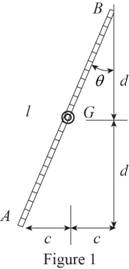
Refer to Figure 1.
Calculate the distance
Substitute
Calculate the distance
Substitute
Sketch the Free Body Diagram of the ladder as shown in Figure 2.
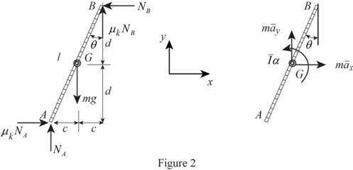
Refer to Figure 2.
Apply the Equations of Equilibrium as shown below.
Apply the Equilibrium of force along x direction as shown below.
Apply the Equilibrium of force along y direction as shown below.
Apply the Equilibrium of moment about G as shown below.
Apply the kinematics as shown below.
Calculate the acceleration
Substitute
Calculate the acceleration
Substitute
Resolving the components of i and j in Equation (5) as shown below.
Calculate the acceleration
Substitute
Hence,
Calculate the reaction
Substitute
Calculate the reaction
Substitute
Calculate the reaction
Substitute
Calculate the angular acceleration
Substitute
Substitute
Hence, the angular acceleration of the ladder is
(b)
Find the forces at A and B
(b)
Answer to Problem 16.119P
The force at A is
The force at B is
Explanation of Solution
Given information:
The weight of the ladder is
The length of the ladder is
The coefficient of kinetic friction is
The angle is
Calculation:
Refer to part (a).
The angular acceleration of the ladder is
Calculate the reaction
Substitute
Calculate the force at A
Substitute
Hence, the force at A is
Calculate the reaction
Substitute
Calculate the force at B
Substitute
Therefore, the force at B is
Want to see more full solutions like this?
Chapter 16 Solutions
Vector Mechanics for Engineers: Statics and Dynamics


- The double pulley shown has a weight of 35.0 lb and a centroidal radius of gyration of 5.0 in. Cylinder A (25.0 lb) and block B (16 lb) are attached to cords that wrap around pulleys in the manner shown. The coefficient of kinetic friction between block B and the surface is 0.25. Knowing that the system is released from rest at the position shown (h = 4 ft), determine the velocity of cylinder A when it strikes the ground. 6 in. A h 10 in. Barrow_forward. 16.23 A 20-lb uniform disk is placed in contact with an inclined surface and a constant 7.5 lb ft couple M is applied as shown. The weight of the link AB is negligible. Knowing that the coefficient of kinetic friction at D is 0.4, de- termine (a) the angular acceleration of the disk, (b) the force in the link AB. 9 in Fig. P16.23 and P16.24 Darrow_forwardThe 10-in.-radius brake drum is attached to a larger flywheel which is not shown. The total mass moment of inertia of the flywheel and drum is 22 lb ⋅ ft ⋅ s 2 and the coefficient of kinetic friction between the drum and the brake shoe is 0.41. Knowing that the initial angular velocity is 255 rpm clockwise, determine the force which must be exerted by the hydraulic cylinder at point B if the system is to stop in 85 revolutions. DO NOT ROUND OFF IN THE SOLUTION. ROUND OFF ONLY THE FINAL ANSWERarrow_forward
- The 10-in.-radius brake drum is attached to a larger flywheel which is not shown. The total mass moment of inertia of the flywheel and drum is 22 lb ⋅ ft ⋅ s 2 and the coefficient of kinetic friction between the drum and the brake shoe is 0.41. Knowing that the initial angular velocity is 255 rpm clockwise, determine the force which must be exerted by the hydraulic cylinder at point B if the system is to stop in 85 revolutions.arrow_forwardThe 10-in.-radius brake drum is attached to a larger flywheel which is not shown. The total mass moment of inertia of the flywheel and drum is 22 lb ⋅ ft ⋅ s 2 and the coefficient of kinetic friction between the drum and the brake shoe is 0.41. Knowing that the initial angular velocity is 255 rpm clockwise, determine the force which must be exerted by the hydraulic cylinder at point B if the system is to stop in 85 revolutions. determine the force which must be exerted by the hydraulic cylinder at point B if the system is to stop in 85 revolutions. DO NOT ROUND OFF IN THE SOLUTION. ROUND OFF ONLY IN 2 DECIMAL PLACE IN THE FINAL ANSWER.arrow_forwardQ3. The double pulley shown in Fig Q3 has a mass of 14 kg and a centroidal radius of gyration of 165 mm. A and B are attached to cords that are wrapped around the pulley. µk = 0.25 between B and the surface. A friction moment exists in the axle of the pulley of 0.8 Nm. Knowing the system is released from rest, at the position shown, Using hand Calculations to determine, a) The velocity of A as it strikes the ground b) The total distance covered by B before it comes to rest. Using MATLAB to plot the variation of the velocity with the work done by the system. 250 mm 150 mm Not to scale m, = 9 kg B A m, = 11.5 kg 900 mm Fig. Q3arrow_forward
- The 200-mm-radius brake drum is attached to a larger Bywheel. The total mass moment of inertia of the flywheel and drum is 19 kg. and the coefficient of kinetic friction between the drum and the brake shoe is 035, Knowing that the initial angular velocity of the flywheel is 180 rpm clockwise, determine the vertical force P that must be applied to the pedal C if the system is to stop in 100 revolutions. 150 mm 250 mm B ne: P= 172.88 N C 375 mm 200 mmarrow_forward16.5 A uniform rod BC of mass 4 kg is connected to a collar A by a 250-mm cord AB. Neglecting the mass of the collar and cord, determine (a) the smallest constant acceleration a, for which the cord and the rod will lie in a straight line, (b) the corresponding tension in the cord. 250 mm B 400 mm 350 mm Fig. P16.5 Carrow_forwardBlock A of Fig.(3) weighs 100N and block B weighs 300N. The coefficient of static friction between the blocks is 0.5, and the coefficient of kinetic friction between block B and the plane is 0.25. Determine the max. value of (P) that may be applied without causing block A to slide on block B when block B is moving to the left. (The gravitational acceleration is 10 m/s?) P. AT00 24 300 Fig.(3) m.ax Good Luck Pt N ray 2-2 B.arrow_forward
- 3. The 10-in.-radius brake drum is attached to A a larger flywheel which is not shown. The total mass moment of inertia of the flywheel and drum is 16 lb · ft · s² and the coefficient of kinetic 6 in. friction between the drum and the brake shoe is В 0.40. Knowing that the initial angular velocity is 240 rpm clockwise, determine the force which must be exerted by the hydraulic cylinder if the system is to stop in 75 revolutions. 12 in. D Use work-energy equation. 10 in. +6 in.-arrow_forward16.8 A load of lumber weighing W = 25 kN is being raised by a crane. The weight of the boom ABC is 3 kN and the combined weight of the truck and driver is 50 kN as shown. Determine the maximum vertical acceleration of the lumber so that the crane does not tip over. A W 2.0 m- 2.0 m- Fig. P16.8 0.6 m 0.4 m ty B 3 kN F H 0.9 m C D 0.3 m -E 50 kN 2.0 m- K k 0.5 marrow_forwardA garage door is mounted on an overhead rail. The wheels at A and B have rusted so that they do not roll, but rather slide along the track. The coefficient of kinetic friction is 0.55. The distance between the wheels is 2.00 m, and each is 0.50m from the vertical sides of the door. The door is uniform and weighs 850 N. It is pushed to the left at constant speed by a horizontal force F⃗, that is applied as shown in the figure. If the distance h is 1.60 m, what is the vertical component of the force exerted on the wheel A by the track? If the distance h is 1.60 m, what is the vertical component of the force exerted on the wheel B by the track? Find the maximum value hh can have without causing one wheel to leave the track.arrow_forward
 Elements Of ElectromagneticsMechanical EngineeringISBN:9780190698614Author:Sadiku, Matthew N. O.Publisher:Oxford University Press
 Mechanics of Materials (10th Edition)Mechanical EngineeringISBN:9780134319650Author:Russell C. HibbelerPublisher:PEARSON
 Thermodynamics: An Engineering ApproachMechanical EngineeringISBN:9781259822674Author:Yunus A. Cengel Dr., Michael A. BolesPublisher:McGraw-Hill Education
 Control Systems EngineeringMechanical EngineeringISBN:9781118170519Author:Norman S. NisePublisher:WILEY
 Mechanics of Materials (MindTap Course List)Mechanical EngineeringISBN:9781337093347Author:Barry J. Goodno, James M. GerePublisher:Cengage Learning
 Engineering Mechanics: StaticsMechanical EngineeringISBN:9781118807330Author:James L. Meriam, L. G. Kraige, J. N. BoltonPublisher:WILEY