
a.
The expression for the frequency of the oscillation.
a.
Answer to Problem 15.29P
The expression for the frequency of oscillation:
Explanation of Solution
Given:
The circuit is given as:
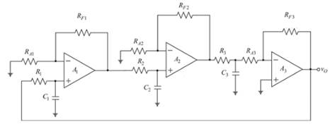
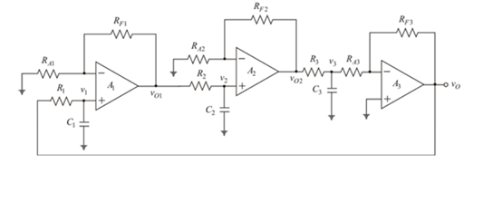
The circuit is redrawn by labeling the voltages as shown below:
Assuming:
Considering
Nodal analysis at the node
The amplifier gain of
Now, the output of
The nodal analysis at the node
Applying the nodal analysis at the inverting terminal of the
Solving equation (3):
Now, solving the equation (1):
Evaluating the frequency of the oscillation, use
Now, equating the imaginary values to 0:
Squaring the both sides:
Hence, the needed expression for the frequency of oscillation:
b.
The condition for the oscillation.
b.
Answer to Problem 15.29P
The condition for oscillation:
Explanation of Solution
Given:
The circuit is given as:
When,
The condition for oscillation:
Taking
Hence, the needed condition for oscillation:
c.
The condition for the oscillation.
c.
Answer to Problem 15.29P
The condition for oscillation:
Explanation of Solution
Given:
The circuit is given as:

Now substituting the values in equation 4:
Hence, the condition for the oscillation:
Want to see more full solutions like this?
Chapter 15 Solutions
Microelectronics: Circuit Analysis and Design

- Consider a step down converter supplied by a DC power source of magnitude Vs = 220 V. The switching period is 0.1 ms and the duty cycle k is set to 0.5. The load is an inductive load with R-S Ohms and L-10 mH. The switch is ideal. The RMS converter current IR is equal to 15.56A. The ripple factor of the input current RFs would be equal to: Select one: O a. None of these O b. 0% OC. 100% O d. 50%arrow_forward6) In digital frequency meter, Schmitt trigger converts input signal into a ............ wave, which has a fast rise and fall time.arrow_forwardDetermine the noise power for the figure shown below. Simulation Settings SNR 31.623 SNR 15.0 dB Signal Generator - Properties Amplitude > 1.35 V Frequency > 0.2 kHz Output On Waveform Sine O a. 0.028816 mV^2 O b. 0.06075 V^2 c. 57.632 mV^2 O d, 28.816 mV^2arrow_forward
- B- An rate. analog signal having single frequency as 3 kHz is sampled with 5 kHz S Describe its frequency spectrum. What will be the output if the sampled signals a passed through a low-pass filter having cutoff frequency at 2.5 kHz? signal. are sent in the analogarrow_forwardWhat is Frequency Modulation? Draw the waveforms.arrow_forwardWhat is a filter? An active filter? Give one application for an active filter.arrow_forward
- eliminate any redundant form...arrow_forwardHononta (Vj Ais M QUESTION (1) pressure signal from a force transducer is given as under. Analyze it in terms of harmonics, amplitude, circular frequency, cyclic frequency, time period and phase. A. P=15 sin(20m + +12 sin(40t-)+10sin(60t +)+8sin(100zt +")+5sin(140nt -"). +3sin(180) Pa %3Darrow_forwardConsider a step down converter with a resistive load. It is supplied by a DC power source of magnitude Vs = 160 V. The switching period is 0.25 ms and the duty cycle k is first set to 0.5. The load is an inductive load with R=10 Ohms and L-10 mH. The switch is ideal. The average source current is 4A. The ripple factor of the input current RFs is equal to: Select one: O a. None of these O b. 0% C. 100% d. 50% Clear my choicearrow_forward
- A voltage commutated chopper operating at 1 kHz is used to control the speed of dc motor as shown in figure. The load current is assumed to be constant at 10 A. 00000 V = 250 V 1₁F XA vous 2mH The minimum time in uses for which the SCR M should be ON isarrow_forwardVcc=15V Q1: BC237 Rc 3.6kQ or BC238 B=200 VBE(on)=0.7V R1 110KQ Rs Cci 1000 4.7µF Cco 4.7µF R2 ·27kΩ RE 1.2kQ RL 12kΩ Vs Rin Rout Figure 1. Common-emitter amplifier. 2)arrow_forwardA three phase full controlled converter is supplied by a phase voltage Vs=120V, 60 Hz. Consider a resistive load R=10 Q. Suppose that the average output voltage is 25% of the maximum possible average output voltage. The delay angle a would be equal to: Select one: a. 45.52deg O b. 57.9deg O c. 27.52deg O d. 75.52degarrow_forward
 Introductory Circuit Analysis (13th Edition)Electrical EngineeringISBN:9780133923605Author:Robert L. BoylestadPublisher:PEARSON
 Delmar's Standard Textbook Of ElectricityElectrical EngineeringISBN:9781337900348Author:Stephen L. HermanPublisher:Cengage Learning
 Programmable Logic ControllersElectrical EngineeringISBN:9780073373843Author:Frank D. PetruzellaPublisher:McGraw-Hill Education
 Fundamentals of Electric CircuitsElectrical EngineeringISBN:9780078028229Author:Charles K Alexander, Matthew SadikuPublisher:McGraw-Hill Education
 Electric Circuits. (11th Edition)Electrical EngineeringISBN:9780134746968Author:James W. Nilsson, Susan RiedelPublisher:PEARSON
 Engineering ElectromagneticsElectrical EngineeringISBN:9780078028151Author:Hayt, William H. (william Hart), Jr, BUCK, John A.Publisher:Mcgraw-hill Education,