
Shigley's Mechanical Engineering Design (McGraw-Hill Series in Mechanical Engineering)
10th Edition
ISBN: 9780073398204
Author: Richard G Budynas, Keith J Nisbett
Publisher: McGraw-Hill Education
expand_more
expand_more
format_list_bulleted
Concept explainers
Videos
Textbook Question
Chapter 13, Problem 38P
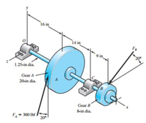
For the countershaft in Prob. 3-72, p. 152, assume the gear ratio from gear B to its mating gear is 2 to 1.
- (a) Determine the minimum number of teeth that can be used on gear B without an interference problem in the teeth.
- (b) Using the number of teeth from part (a), what diametral pitch is required to also achieve the given 8-in pitch diameter?
- (c) Suppose the 20° pressure angle gears are exchanged for gears with 25° pressure angle, while maintaining the same pitch diameters and diametral pitch. Determine the new forces FA and FB if the same power is to be transmitted.
Problem 3-72*
Expert Solution & Answer
Want to see the full answer?
Check out a sample textbook solution
Students have asked these similar questions
(b)
Solve the base pitch, centre distance, whole depth and contact ratio of a gear with
the given parameters: Pa= 6, 20 degree pressure angle, 19-tooth pinion is meshed
with a 77-tooth gear.
1. honano aean
--. . -a..k hooi sohuch
(c)
Solve the contact ratio of a gear when the base pitch, P, is the same length of action,
Z in Question Q2(b).
[Selesaikan nisbah sentuh gear apabila jarak benang asas, Ps adalah sama Panjang Tindakan, Z
dalam Soalan Q2(b).]
If this gear (Q2(b)) is a one of the component needed for designing a compound
gear train with ratio at 150:1, design the gear.
[Jika gear ini adalah salah satu komponen yang akan digunakan untuk merekabentuk 'train'
kompaun gear pada nisbah 150:1, rekabentuk gear ini.
(d)
A shaft carrying gear “A" rotates at 1750 rpm clockwise. What is the rotational speed and
rotational direction of the output gear "E"? (Refer to the figure below).
Input
Shaft 1
NA = 20
Only pitch
circles of
gears shown
BNg= 70
(A)
(B)
(C)
(D)
(E)
Nc = 18
166.7 rpm, CW
Shaft 2
166.7 rpm, CCW
203.7 rpm, CW
DND 22
203.7 rpm, CCW
Shaft 3
E
409.1 rpm, CCW
Note: Gear D is
Ng= 54
E
an idier
Shaft 4
Output
ASAP
Chapter 13 Solutions
Shigley's Mechanical Engineering Design (McGraw-Hill Series in Mechanical Engineering)
Ch. 13 - A 17-tooth spur pinion has a diametral pitch of 8...Ch. 13 - A 15-tooth spur pinion has a module of 3 mm and...Ch. 13 - A spur gearset has a module of 6 mm and a velocity...Ch. 13 - A 21-tooth spur pinion mates with a 28-tooth gear....Ch. 13 - A 20 straight-tooth bevel pinion having 14 teeth...Ch. 13 - A parallel helical gearset uses a 20-tooth pinion...Ch. 13 - A parallel helical gearset consists of a 19-tooth...Ch. 13 - To avoid the problem of interference in a pair of...Ch. 13 - Prob. 9PCh. 13 - Prob. 10P
Ch. 13 - Prob. 11PCh. 13 - Prob. 12PCh. 13 - Prob. 13PCh. 13 - Prob. 14PCh. 13 - A parallel-shaft gearset consists of an 18-tooth...Ch. 13 - The double-reduction helical gearset shown in the...Ch. 13 - Shaft a in the figure rotates at 600 rev/min in...Ch. 13 - The mechanism train shown consists of an...Ch. 13 - The figure shows a gear train consisting of a pair...Ch. 13 - A compound reverted gear trains are to be designed...Ch. 13 - Prob. 21PCh. 13 - Prob. 22PCh. 13 - Prob. 23PCh. 13 - A gearbox is to be designed with a compound...Ch. 13 - The tooth numbers for the automotive differential...Ch. 13 - Prob. 26PCh. 13 - In the reverted planetary train illustrated, find...Ch. 13 - Prob. 28PCh. 13 - Tooth numbers for the gear train shown in the...Ch. 13 - The tooth numbers for the gear train illustrated...Ch. 13 - Shaft a in the figure has a power input of 75 kW...Ch. 13 - The 24T 6-pitch 20 pinion 2 shown in the figure...Ch. 13 - The gears shown in the figure have a module of 12...Ch. 13 - The figure shows a pair of shaft-mounted spur...Ch. 13 - Prob. 35PCh. 13 - Prob. 36PCh. 13 - A speed-reducer gearbox containing a compound...Ch. 13 - For the countershaft in Prob. 3-72, p. 152, assume...Ch. 13 - Prob. 39PCh. 13 - Prob. 40PCh. 13 - Prob. 41PCh. 13 - Prob. 42PCh. 13 - The figure shows a 16T 20 straight bevel pinion...Ch. 13 - The figure shows a 10 diametral pitch 18-tooth 20...Ch. 13 - Prob. 45PCh. 13 - The gears shown in the figure have a normal...Ch. 13 - Prob. 47PCh. 13 - Prob. 48PCh. 13 - Prob. 49PCh. 13 - The figure shows a double-reduction helical...Ch. 13 - A right-hand single-tooth hardened-steel (hardness...Ch. 13 - The hub diameter and projection for the gear of...Ch. 13 - A 2-tooth left-hand worm transmits 34 hp at 600...
Knowledge Booster


Learn more about
Need a deep-dive on the concept behind this application? Look no further. Learn more about this topic, mechanical-engineering and related others by exploring similar questions and additional content below.Similar questions
- 5.A pair of gears has these parameters: teeth of two gears are Z1=26, Z2=52, modulus m=1.25mm. Please calculate (1)the radius of reference circle of two gears, r1 and r2 (2) The pitch of this pair of gears, p (3) The standard center distance, a (4) Now two gears are mounted with a'=49mm, calculate the radius of two pitch circle for two gears, r1' and r2' . (5)The ratio of angular velocity of two gears, i.arrow_forwardThe figure shows a schematic representation of a gear system. The gears are meshed with one another and can therefore not slip. The ring gear R is fixed, i.e. wR = 0. Gear A has an inner hub with radius rA(inner) = 0.3 m which is fixed to the rest of the gear, having a radius of FAlouter) = 0.8 m, and moves together as a unit. Gear A is in mesh with gear B which has a diameter of de = 1.5 m. Gear B has a clockwise angular velocity of wg = 2.1 rad/s. Determine the angular speed of gear A. B TA(outer Rarrow_forwardQ.7 A pair of parallel helical gears consists of a 20 teeth pinion mashing with a 40 teeth gear. The helix angle is 25° and normal pressure angle is 20°. The normal module is 3 mm. Calculatc () The transverse module. (ii) The transverse pressure angle. (ii) The axial pitch. (tv) Pitch circle diameters of pinion and gear. (v) Center distance.arrow_forward
- The top half of a compound Epicyclic gearset is shown in Figure, with input shaft I rotating at a constant speed of 700 rpm in a clockwise direction and generating 12 kW input power. The Annulus wheel A2 isform a compound wheel with gear O and connected to an auxiliary gear N on shaft X. . The Annulus A1 rotates in a counter-clockwise direction at a speed of 5,300 rpm. Calculate the following using this condition: The speed and direction of output shaft O (NO), shaft X (NX) and gear ratio (n). If Annulus wheel A1 is locked calculate the speed and direction of output shaft O (NO), shaft X (NX) and gear ratio (n). The braking torque (Tb) (magnitude and direction) that must be applied to Annulus wheel A1 to hold it stationary, assuming gear transmission efficiency is 90%. Number of gear teeth:P1 = 30 , A1 = 120P2 = 50 , A2 = 140N = 60 , O = 120arrow_forwardThe upper half of a compound Epicyclic gearset is shown in Figure, with input shaft I rotating at a constant speed of 700 rpm in a clockwise direction and generating 12 kW input power. The Annulus wheel A2 is coupled to an auxiliary gear N on shaft X and forms a compound wheel with gear O. The Annulus A1 rotates in a counter-clockwise direction at a speed of 5,300 rpm. Calculate the following using this condition: Number of gear teeth:P1 = 30 , A1 = 120P2 = 50 , A2 = 140N = 60 , O = 120 a) The output shaft O (NO), shaft X (NX), and gear ratio speed and direction (n). b) Calculate the speed and direction of output shaft O (NO), shaft X (NX), and gear ratio if Annulus wheel A1 is locked (n). c) The braking torque (Tb) that must be applied to Annulus wheel A1 to keep it stationary (magnitude and direction), assuming gear transmission efficiency of 90%.arrow_forwardQ4: The reverted gear train shown in Fig.(1) has the following data, Circular pitch Pc=0.4 teeth/mm, T1=15, T2=30, T3=20 , N1= 150 rpm (cw) • Determine: • 1. module of gear train (m3D?) 4 Output Input 2.Pitch diameter of gears (D1, D2, D3, D4) 3. The centre distance between shafts (C) • 4. Gear ratio (G), and Train value (TV) 5. output speed (N4)arrow_forward
- Q4: The reverted gear train shown in Fig.(1) has the following data, Circular pitch Pc=D0.4 teeth/mm , T1=15, T2=30, T3=20 , N1= 150 rpm (cw) Determine: • 1. module of gear train (m3?) Output Input 2.Pitch diameter of gears (D1, D2, D3, D4) 3. The centre distance between shafts (C) • 4. Gear ratio (G), and Train value (TV) • 5. output speed (N4) 4/14/2020 27arrow_forward7. The following data relate to a pair of 20° involute gears in mesh : Module = 6 mm, Number of teeth on pinion = 17, Number of teeth on gear = 49; Addenda on pinion and gear wheel = 1 module. Find : (a) The number of pairs of teeth in contact (b) The angle turned through by the pinion and the gear wheel when one pair of teeth is in contact (c) The ratio of sliding to rolling motion when the tip of a tooth on the larger wheel (i) is just making contact (ii) is just leaving contact with its mating tooth (iii) is at the pitch point.arrow_forwardFor a pair of standard gears, the module is m=2.5mm,pressure angle is α=20 0. ha*=1. c*=0.25. The teeth number on gear 1 is z1=22. The standard center distance is a=68.75mm. Find the following parameters of gear 2: the teeth number, z2 = ( ) the diameter of reference circle, d2=( )mm the diameter of addendum circle da2 =( )mm the diameter of dedendum circle df2 =( )mmarrow_forward
- A parallel helical gearset uses a 20-tooth pinion driving a 46-tooth gear. The pinion has a righthand helix angle of 30◦, a normal pressure angle of 20◦, and a normal diametral pitch of 6 teeth/in. Find: (a) The normal, transverse, and axial circular pitches (b) The normal base circular pitch (c) The transverse diametral pitch and the transverse pressure angle (d) The addendum, dedendum, and pitch diameter of each geararrow_forwardQ6: The reverted gear train shown in figure has the following data, Gear ratio, G=15 • Modules: m1=3 mm (1&2), m2=2.5 (3&4) The center distance between shafts, x=250 (output) 4 3 mm Determine the suitable numbers of teeth for the gears (input) 1 2 4/14/2020 29arrow_forwardStraight bevel gears are mainly used to change the change the rotation axis of intersecting shafts. You work as a maintenance engineer for a food packaging company and your supervisor asked you to accurately calculate the dimensions for a set of straight bevel gears used in one of the differential gearboxes at the facility. The gear type is an uncrowned straight-bevel pinion has 22 teeth, a module of 4.5 mm, and a transmission accuracy number of 5. The pinion and the gear are made of through-hardened steel, both having core and case hardnesses of 210 Brinell. The pinion drives the 24-tooth bevel gear. The shaft angle is 90°, the pinion speed is 1600 rev/min, the face width is 23 mm, and the normal pressure angle is 20°. Both gears have an outboard mounting. Find: a) The power rating based on AGMA pitting resistance if the life goal is 10° revolutions of the pinion at 0.98 reliability.arrow_forward
arrow_back_ios
SEE MORE QUESTIONS
arrow_forward_ios
Recommended textbooks for you
 Elements Of ElectromagneticsMechanical EngineeringISBN:9780190698614Author:Sadiku, Matthew N. O.Publisher:Oxford University Press
 Mechanics of Materials (10th Edition)Mechanical EngineeringISBN:9780134319650Author:Russell C. HibbelerPublisher:PEARSON
 Thermodynamics: An Engineering ApproachMechanical EngineeringISBN:9781259822674Author:Yunus A. Cengel Dr., Michael A. BolesPublisher:McGraw-Hill Education
 Control Systems EngineeringMechanical EngineeringISBN:9781118170519Author:Norman S. NisePublisher:WILEY
 Mechanics of Materials (MindTap Course List)Mechanical EngineeringISBN:9781337093347Author:Barry J. Goodno, James M. GerePublisher:Cengage Learning
 Engineering Mechanics: StaticsMechanical EngineeringISBN:9781118807330Author:James L. Meriam, L. G. Kraige, J. N. BoltonPublisher:WILEY
Elements Of Electromagnetics
Mechanical Engineering
ISBN:9780190698614
Author:Sadiku, Matthew N. O.
Publisher:Oxford University Press
Mechanics of Materials (10th Edition)
Mechanical Engineering
ISBN:9780134319650
Author:Russell C. Hibbeler
Publisher:PEARSON
Thermodynamics: An Engineering Approach
Mechanical Engineering
ISBN:9781259822674
Author:Yunus A. Cengel Dr., Michael A. Boles
Publisher:McGraw-Hill Education
Control Systems Engineering
Mechanical Engineering
ISBN:9781118170519
Author:Norman S. Nise
Publisher:WILEY
Mechanics of Materials (MindTap Course List)
Mechanical Engineering
ISBN:9781337093347
Author:Barry J. Goodno, James M. Gere
Publisher:Cengage Learning
Engineering Mechanics: Statics
Mechanical Engineering
ISBN:9781118807330
Author:James L. Meriam, L. G. Kraige, J. N. Bolton
Publisher:WILEY
Power Transmission; Author: Terry Brown Mechanical Engineering;https://www.youtube.com/watch?v=YVm4LNVp1vA;License: Standard Youtube License