
Mechanics of Materials
11th Edition
ISBN: 9780137605460
Author: Russell C. Hibbeler
Publisher: Pearson Education (US)
expand_more
expand_more
format_list_bulleted
Concept explainers
Videos
Textbook Question
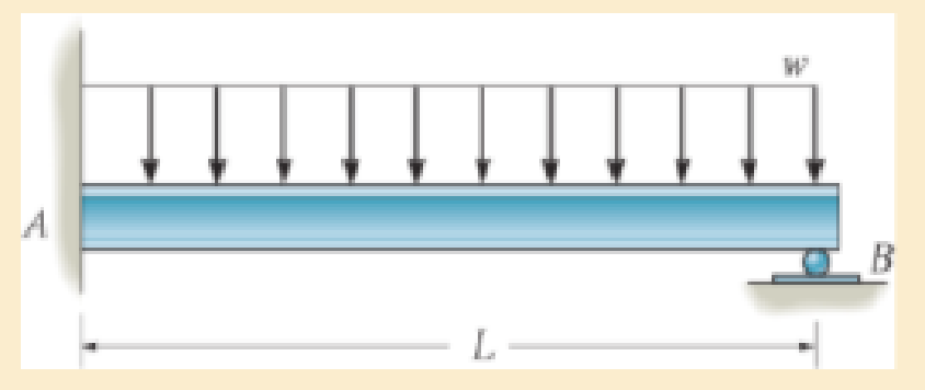
Chapter 12.7, Problem 103P
Determine the reactions at the supports A and B, then draw the shear and moment diagrams. El is constant.
Expert Solution & Answer
Want to see the full answer?
Check out a sample textbook solution
Students have asked these similar questions
Determine the magnitude of the moment reaction. Take the angle a = 77 °, b = 47 ° and F = 283N
Find the deformation and the reaction at A and B.
Determine the reactions at support A and draw the shear force and bending moment diagrams of the beam. Also indicate the maximum values of shear force and bending moment.
Chapter 12 Solutions
Mechanics of Materials
Ch. 12.2 - Determine the slope and deflection of end A of the...Ch. 12.2 - Determine the slope and deflection of end A of the...Ch. 12.2 - Determine the slope of end A of the cantilevered...Ch. 12.2 - Determine the maximum deflection of the simply...Ch. 12.2 - Determine the maximum deflection of the simply...Ch. 12.2 - Determine the slope of the simply supported beam...Ch. 12.2 - An L2 steel strap having a thickness of 0.125 in....Ch. 12.2 - The L2 steel blade of the band saw wraps around...Ch. 12.2 - A picture is taken of a man performing a pole...Ch. 12.2 - A torque wrench is used to tighten the nut on a...
Ch. 12.2 - The pipe can be assumed roller supported at its...Ch. 12.2 - Determine the equations of the elastic curve for...Ch. 12.2 - Determine the equations of the elastic curve using...Ch. 12.2 - Determine the maximum deflection of the solid...Ch. 12.2 - Determine the equation of the elastic curve using...Ch. 12.2 - Determine the equations of the elastic curve using...Ch. 12.3 - The shaft supports the two pulley loads shown....Ch. 12.3 - Determine the equation of the elastic curve, the...Ch. 12.3 - Determine the equation of the elastic curve and...Ch. 12.3 - Determine the maximum deflection of the...Ch. 12.3 - Prob. 45PCh. 12.3 - Prob. 46PCh. 12.3 - Prob. 47PCh. 12.3 - Prob. 48PCh. 12.4 - Determine the slope and deflection of end A of the...Ch. 12.4 - Determine the slope and deflection of end A of the...Ch. 12.4 - Determine the slope and deflection of end A of the...Ch. 12.4 - Determine the slope and deflection at A of the...Ch. 12.4 - Prob. 11FPCh. 12.4 - Determine the maximum deflection of the simply...Ch. 12.4 - Determine the slope and deflection at C. El is...Ch. 12.4 - Prob. 54PCh. 12.4 - The composite simply supported steel shaft is...Ch. 12.4 - Determine the maximum deflection of the...Ch. 12.4 - Prob. 60PCh. 12.4 - Determine the slope at A and the maximum...Ch. 12.4 - Determine the displacement of the 20-mm-diameter...Ch. 12.4 - The two force components act on the tire of the...Ch. 12.4 - Determine the slope at B and deflection at C. El...Ch. 12.4 - Prob. 79PCh. 12.5 - The W10 15 cantilevered beam is made of A-36...Ch. 12.5 - The W14 43 simply supported beam is made of A992...Ch. 12.5 - The W14 43 simply supported beam is made of A992...Ch. 12.5 - The W14 43 simply supported beam is made of A-36...Ch. 12.7 - Determine the reactions at the supports A and B,...Ch. 12.7 - Determine the reactions at the supports A, B, and...Ch. 12.7 - Determine the reactions at the supports A and B,...Ch. 12.7 - The beam has a constant E1I1 and is supported by...Ch. 12.8 - Determine the reaction at the supports, then draw...Ch. 12.9 - Determine the reactions at the fixed support A and...Ch. 12.9 - Determine the reactions at the fixed support A and...Ch. 12.9 - Determine the reactions at the fixed support A and...Ch. 12.9 - Determine the reaction at the roller B. EI is...Ch. 12.9 - Determine the reaction at the roller B. EI is...Ch. 12.9 - Determine the reaction at the roller support B if...Ch. 12.9 - Determine the reactions at the journal bearing...Ch. 12.9 - Determine the reactions at the supports, then draw...Ch. 12.9 - Determine the reactions at the supports, then draw...Ch. 12.9 - The rim on the flywheel has a thickness t, width...Ch. 12.9 - Determine the moment developed in each corner....Ch. 12 - Determine the equation of the elastic curve. Use...Ch. 12 - Draw the bending-moment diagram for the shaft and...Ch. 12 - Determine the moment reactions at the supports A...Ch. 12 - Specify the slope at A and the maximum deflection....Ch. 12 - Determine the maximum deflection between the...Ch. 12 - Determine the slope at B and the deflection at C....Ch. 12 - Determine the reactions, then draw the shear and...Ch. 12 - El is constant.Ch. 12 - Using the method of superposition, determine the...
Additional Engineering Textbook Solutions
Find more solutions based on key concepts
The moment of inertia Iy for the slender rod in terms of the rod’s total mass m .
Engineering Mechanics: Statics & Dynamics (14th Edition)
A number of common substances are
Some of these materials exhibit characteristics of both solid and fluid beha...
Fox and McDonald's Introduction to Fluid Mechanics
19.8 Calculate the allowable tensile load for the connection shown. The plates are ASTM A36 steel and the weld ...
Applied Statics and Strength of Materials (6th Edition)
The triple jump is a track-and-field event in which an athlete gets a running start and tries to leap as far as...
Vector Mechanics For Engineers
Locate the centroid of the area. Prob. 9-17
INTERNATIONAL EDITION---Engineering Mechanics: Statics, 14th edition (SI unit)
What is the weight in newtons of an object that has a mass of (a) 8 kg, (b) 0.04 kg, (c) 760 Mg?
Statics and Mechanics of Materials (5th Edition)
Knowledge Booster


Learn more about
Need a deep-dive on the concept behind this application? Look no further. Learn more about this topic, mechanical-engineering and related others by exploring similar questions and additional content below.Similar questions
- 1. Determine the reaction and moment at point A and draw the Shear force and Bending moment diagramsarrow_forwardDetermine the magnitude of the moment reaction. Consider a = 78 ° and b = 69 °, F = 459N.arrow_forward8 kN/m 9m 6 m B C 4 kN/m Show Transcribed Text Determine the reactions at the supports using the force method. Moreover, draw the moment diagram. El is constant.arrow_forward
- Determine the reactions at the supports A and B, then draw the moment diagram. EI is constant.arrow_forwardDetermine the internal normal force, shear force, and the moment at points C and D.arrow_forwardA reinforced concrete pier is used to support the stringers for a bridge deck. Draw the shear and moment diagrams for the pier. Assume the columns at A and B exert only vertical reactions on the pier.arrow_forward
- determine the reactions at the supports A and B, then draw the shear and moment diagram. EI is constant. neglect the effect of axial loadarrow_forwardThe beam is subjected to a load F = 275 N and is supported by the rope and the smooth surfaces at A and B. a. Draw the free-body diagram of the beam. b. What are the magnitudes of the reactions at A and B?arrow_forwardThe multispan girder has two shear plate connections that act as hinges at C and D. The midspan girder CD is simply supported on the cantilevered ends of the left and right girders. Determine the forces in the hinges and the reactions at supports A, B, E, and F. Also draw the shear and moment diagram.arrow_forward
arrow_back_ios
SEE MORE QUESTIONS
arrow_forward_ios
Recommended textbooks for you
 Elements Of ElectromagneticsMechanical EngineeringISBN:9780190698614Author:Sadiku, Matthew N. O.Publisher:Oxford University Press
 Mechanics of Materials (10th Edition)Mechanical EngineeringISBN:9780134319650Author:Russell C. HibbelerPublisher:PEARSON
 Thermodynamics: An Engineering ApproachMechanical EngineeringISBN:9781259822674Author:Yunus A. Cengel Dr., Michael A. BolesPublisher:McGraw-Hill Education
 Control Systems EngineeringMechanical EngineeringISBN:9781118170519Author:Norman S. NisePublisher:WILEY
 Mechanics of Materials (MindTap Course List)Mechanical EngineeringISBN:9781337093347Author:Barry J. Goodno, James M. GerePublisher:Cengage Learning
 Engineering Mechanics: StaticsMechanical EngineeringISBN:9781118807330Author:James L. Meriam, L. G. Kraige, J. N. BoltonPublisher:WILEY
Elements Of Electromagnetics
Mechanical Engineering
ISBN:9780190698614
Author:Sadiku, Matthew N. O.
Publisher:Oxford University Press
Mechanics of Materials (10th Edition)
Mechanical Engineering
ISBN:9780134319650
Author:Russell C. Hibbeler
Publisher:PEARSON
Thermodynamics: An Engineering Approach
Mechanical Engineering
ISBN:9781259822674
Author:Yunus A. Cengel Dr., Michael A. Boles
Publisher:McGraw-Hill Education
Control Systems Engineering
Mechanical Engineering
ISBN:9781118170519
Author:Norman S. Nise
Publisher:WILEY
Mechanics of Materials (MindTap Course List)
Mechanical Engineering
ISBN:9781337093347
Author:Barry J. Goodno, James M. Gere
Publisher:Cengage Learning
Engineering Mechanics: Statics
Mechanical Engineering
ISBN:9781118807330
Author:James L. Meriam, L. G. Kraige, J. N. Bolton
Publisher:WILEY
Understanding Shear Force and Bending Moment Diagrams; Author: The Efficient Engineer;https://www.youtube.com/watch?v=C-FEVzI8oe8;License: Standard YouTube License, CC-BY
Bending Stress; Author: moodlemech;https://www.youtube.com/watch?v=9QIqewkE6xM;License: Standard Youtube License