
Concept explainers
Videos
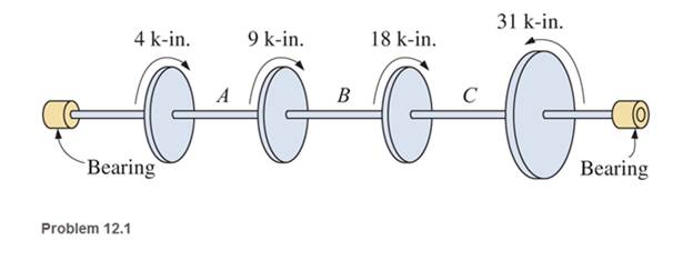
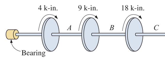
Determine the internal resisting torque in the shaft shown at A, B, and C. Show the free-body diagrams.
The externally resisting torque in the shaft at points A, B, and C
Answer to Problem 12.1P
Explanation of Solution
Given Information:
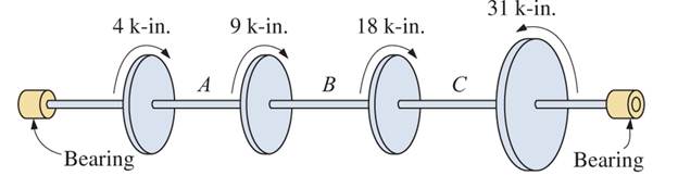
The shaft and torque acting on it are shown in the figure below:
Let internal resisting torque at
Cutting a section at A, take the free body diagram from the left bearing to point A
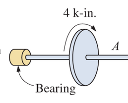
At point A, for equilibrium the summation of torques must be zero
At point B, the free body diagram from the left bearing
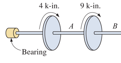
For equilibrium, the summation of torques must be zero
At point C, the free body diagram from the left bearing
For equilibrium, the summation of torques must be zero
Conclusion:
At point A, the internal resisting torque is
At point B the internal resisting torque is
At point C the internal resisting torque is
Want to see more full solutions like this?
Chapter 12 Solutions
Applied Statics and Strength of Materials (6th Edition)
Additional Engineering Textbook Solutions
Engineering Mechanics: Statics & Dynamics (14th Edition)
Applied Fluid Mechanics (7th Edition)
Thinking Like an Engineer: An Active Learning Approach (4th Edition)
INTERNATIONAL EDITION---Engineering Mechanics: Statics, 14th edition (SI unit)
Automotive Technology: Principles, Diagnosis, And Service (6th Edition) (halderman Automotive Series)
Thinking Like an Engineer: An Active Learning Approach (3rd Edition)


- Determine the maximum torque that can be applied to the shaft, given that the maximum angle of twist is 0.0225 rad. Neglect bendingarrow_forwardThe support points (bearings) at A and B only exert force on the components and z, on the steel shaft. Determine the diameter of the shaft, in millimeters, so that it can withstand the gear loads, without exceeding an allowable shear stress ? allowable = 80 MPa.to. Free-Body diagram.b. Shear force diagrams.c. Bending moment diagrams.d. Identification of the critical point of the axis.e. Calculation of the shaft diameter.arrow_forwardThe device shown is used to mix soils in order to provide in-situ stabilization. If the mixer is connected to an A-36 steel tubular shaft that has an inner diameter of 3 in. and an outer diameter of 4.5 in., determine the angle oftwist of the shaft at A relative to C if each mixing blade is subjected to the torques shown.arrow_forward
- 6. Determine the number of 10-mm diameter steel bolts that must be used on the 400-mm bolt circle of the coupling in number 5 to increase the torque capacity to 14 kN-m.arrow_forwardDetermine the value of torque T if the total angle of twist is 4.5o.arrow_forwarda: What is the magnitude of torque applied to the shaft? b: The magnitude of the Polar Moment of Inertia of the shaft cross-section? c: The magnitude of the shear stress at r=0in (center of shaft) is?arrow_forward
- The aluminum shaft, composed of three segments, is fastened to rigid supports at A and D. Calculate the maximum shear stress in each segment when the two torques are appliedarrow_forwardThe triangular plate is fixed at its base, and A is given a horizontal displacement of Δs′= 4 mm. Suppose that L=800 mm.arrow_forwardA solid 0.64-in.-diameter shaft is subjected to the torques shown. The bearings shown allow the shaft to turn freely. Determine the shear stress magnitude in shaft (3).arrow_forward
- (Please input the FBD together with the answer) A flanged bolt coupling consists of nine-in diameter bolts equally spaced around a bolt circle 15 inches in diameter. Determine the torque capacity of the coupling if the shear stress in the bolt is limited to 5000 psi.arrow_forwardhi. can you please help me solve this as for my understanding.. our topic is about Moment of Inertia and I can't understand how it is solve. pls provide a diagram with labels. Thank you 1. Three masses A= 3kg, B= 4kg, and C= 5kg are connected by rods of negligible mass to form an equilateral triangle of side 8m as shown. Determine the individual Torques and total moment of inertia of the system about axis XY. *formula for particles: I = mR^2 (where m=mass; R= radius) *formula for system: I total= summation of I = m1R1^2 + m2R2^2 + ... +mnRn^2 thank you so much for helping me understand our topic.arrow_forwardThe motor delivers 10 hp to the shaft. If it rotates at 1200 rpm, determine the torque produced by the motor.arrow_forward
 International Edition---engineering Mechanics: St...Mechanical EngineeringISBN:9781305501607Author:Andrew Pytel And Jaan KiusalaasPublisher:CENGAGE L