
Vector Mechanics for Engineers: Statics and Dynamics
12th Edition
ISBN: 9781259638091
Author: Ferdinand P. Beer, E. Russell Johnston Jr., David Mazurek, Phillip J. Cornwell, Brian Self
Publisher: McGraw-Hill Education
expand_more
expand_more
format_list_bulleted
Concept explainers
Videos
Textbook Question
Chapter 10.1, Problem 10.25P
In Prob. 10.9, knowing that a = 42 in., b = 28 in., and W = 160 lb, determine the tension T in cable AE when the door is held in the position for which BD = 42 in.
10.9 An overhead garage door of weight W consists of a uniform rectangular panel AC supported by a cable AE attached at the middle of the upper edge of the door and by two sets of frictionless rollers A and B that can slide in horizontal and vertical channels. Express the tension T in cable AE in terms of W, a, b, and θ.
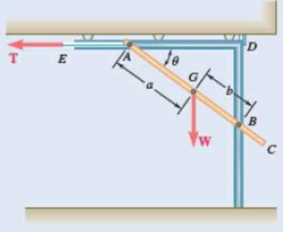
Fig. P10.9
Expert Solution & Answer
Want to see the full answer?
Check out a sample textbook solution
Students have asked these similar questions
In the structure shown, force F is applied at point A at an
angle of e in the direction shown. Pins at G, E, D, B, and
C are all frictionless and all members are weightless. For
the given values of F and e determine:
F= 100 N
0 = 10 deg
A
G
(a) The reactions at points G and E
(b) The forces applied to member GDC at points C and D
(c) The forces applied to member ABC at point B
70 m
50 m
E
D B
Note: components of forces in x and y directions are
enough.
15 m
YA
60 m
20m
In the structure shown, force F is applied at point A at an
angle of 0 in the direction shown. Pins at G, E, D, B, and
C are all frictionless and all members are weightless. For
the given values of F and 0 determine:
F = 50 N
e= 20 deg
A
G
(a) The reactions at points G and E
(b) The forces applied to member GDC at points C and D
(c) The forces applied to member ABC at point B
70 m
50 m
E
D B
Note: components of forces in x and y directions are
enough.
15 m
YA
60 m
20m-
A slender bar of length L = 400 mm is held in equilibrium, with one end touching a
frictionless wall and the other end attached to a wire of length S = 600 mm as illustrated.
Knowing that the weight of the bar is 147 N (which acts at the mid-length of the bar),
determine:
a. the distance h.
b. the tension in the wire.
c. the reaction at B.
C.
В
Chapter 10 Solutions
Vector Mechanics for Engineers: Statics and Dynamics
Ch. 10.1 - Determine the vertical force P that must be...Ch. 10.1 - Determine the horizontal force P that must be...Ch. 10.1 - Prob. 10.3PCh. 10.1 - Prob. 10.4PCh. 10.1 - Prob. 10.5PCh. 10.1 - A spring of constant 15 kN/m connects points C and...Ch. 10.1 - The two-bar linkage shown is supported by a pin...Ch. 10.1 - Determine the weight W that balances the 10-lb...Ch. 10.1 - Prob. 10.9PCh. 10.1 - Prob. 10.10P
Ch. 10.1 - Solve Prob. 10.10, assuming that the force P...Ch. 10.1 - Prob. 10.12PCh. 10.1 - Prob. 10.13PCh. 10.1 - Prob. 10.14PCh. 10.1 - Prob. 10.15PCh. 10.1 - 10.15 and 10.16 Derive an expression for the...Ch. 10.1 - Prob. 10.17PCh. 10.1 - Prob. 10.18PCh. 10.1 - Prob. 10.19PCh. 10.1 - Prob. 10.20PCh. 10.1 - Prob. 10.21PCh. 10.1 - A couple M with a magnitude of 100 Nm isapplied as...Ch. 10.1 - Rod AB is attached to a block at A that can...Ch. 10.1 - Solve Prob. 10.23, assuming that the 800-N force...Ch. 10.1 - In Prob. 10.9, knowing that a = 42 in., b = 28...Ch. 10.1 - Determine the value of corresponding to...Ch. 10.1 - Prob. 10.27PCh. 10.1 - Determine the value of corresponding to...Ch. 10.1 - Prob. 10.29PCh. 10.1 - Two rods AC and CE are connected by a pin at Cand...Ch. 10.1 - Solve Prob. 10.30 assuming that force P is movedto...Ch. 10.1 - Prob. 10.32PCh. 10.1 - Prob. 10.33PCh. 10.1 - Prob. 10.34PCh. 10.1 - Prob. 10.35PCh. 10.1 - Prob. 10.36PCh. 10.1 - Prob. 10.37PCh. 10.1 - Prob. 10.38PCh. 10.1 - Prob. 10.39PCh. 10.1 - Prob. 10.40PCh. 10.1 - Prob. 10.41PCh. 10.1 - The position of boom ABC is controlled by...Ch. 10.1 - Prob. 10.43PCh. 10.1 - Prob. 10.44PCh. 10.1 - Prob. 10.45PCh. 10.1 - Prob. 10.46PCh. 10.1 - Denoting the coefficient of static friction...Ch. 10.1 - Prob. 10.48PCh. 10.1 - Prob. 10.49PCh. 10.1 - Prob. 10.50PCh. 10.1 - Prob. 10.51PCh. 10.1 - Prob. 10.52PCh. 10.1 - Prob. 10.53PCh. 10.1 - Prob. 10.54PCh. 10.1 - Prob. 10.55PCh. 10.1 - Prob. 10.56PCh. 10.1 - Prob. 10.57PCh. 10.1 - Determine the horizontal movement of joint C if...Ch. 10.2 - Using the method of Sec. 10.2C, solve Prob. 10.29....Ch. 10.2 - Prob. 10.60PCh. 10.2 - Prob. 10.61PCh. 10.2 - Prob. 10.62PCh. 10.2 - Prob. 10.63PCh. 10.2 - Prob. 10.64PCh. 10.2 - Prob. 10.65PCh. 10.2 - Using the method of Sec. 10.2C, solve Prob. 10.38....Ch. 10.2 - Prob. 10.67PCh. 10.2 - Prob. 10.68PCh. 10.2 - Prob. 10.69PCh. 10.2 - Prob. 10.70PCh. 10.2 - Prob. 10.71PCh. 10.2 - Prob. 10.72PCh. 10.2 - Prob. 10.73PCh. 10.2 - Prob. 10.74PCh. 10.2 - A load W of magnitude 144 lb is applied to...Ch. 10.2 - Solve Prob. 10.75, assuming that the spring...Ch. 10.2 - Bar ABC is attached to collars A and B that...Ch. 10.2 - Solve Prob. 10.77, assuming that the spring...Ch. 10.2 - Prob. 10.79PCh. 10.2 - Prob. 10.80PCh. 10.2 - Prob. 10.81PCh. 10.2 - A spring AB of constant k is attached to two...Ch. 10.2 - Prob. 10.83PCh. 10.2 - Prob. 10.84PCh. 10.2 - Prob. 10.85PCh. 10.2 - Prob. 10.86PCh. 10.2 - Prob. 10.87PCh. 10.2 - Prob. 10.88PCh. 10.2 - Prob. 10.89PCh. 10.2 - Prob. 10.90PCh. 10.2 - Prob. 10.91PCh. 10.2 - Prob. 10.92PCh. 10.2 - Prob. 10.93PCh. 10.2 - Prob. 10.94PCh. 10.2 - Prob. 10.95PCh. 10.2 - Prob. 10.96PCh. 10.2 - Bars AB and BC, each with a length l and of...Ch. 10.2 - Solve Prob. 10.97 knowing that l = 30 in. and k =...Ch. 10.2 - Bars AB and CD, each of length l and of negligible...Ch. 10.2 - Solve Prob. 10.99, assuming that the vertical...Ch. 10 - Determine the vertical force P that must be...Ch. 10 - Determine the couple M that must be applied...Ch. 10 - Prob. 10.103RPCh. 10 - Prob. 10.104RPCh. 10 - Prob. 10.105RPCh. 10 - Prob. 10.106RPCh. 10 - Prob. 10.107RPCh. 10 - Prob. 10.108RPCh. 10 - Prob. 10.109RPCh. 10 - Prob. 10.110RPCh. 10 - Prob. 10.111RPCh. 10 - Prob. 10.112RP
Knowledge Booster


Learn more about
Need a deep-dive on the concept behind this application? Look no further. Learn more about this topic, mechanical-engineering and related others by exploring similar questions and additional content below.Similar questions
- F= 150 N In the structure shown, force F is applied at point A at an angle of 0 in the direction shown. Pins at G, E, D, B, and C are all frictionless and all members are weightless. For the given values of F and 0 determine: F 0 = 40 deg A G (a) The reactions at points G and E (b) The forces applied to member GDC at points C and D (c) The forces applied to member ABC at point B 70 m 50 m E D B Note: components of forces in x and y directions are enough. 15 m YA 60 m 20m ALL WORK MUST BE SHOWN (FBDS, EQUATIONS, etc.). CORRECT ANSWERS WITHOUT CLEAR EVIDENCE OF HOW THEY WERE OBTAINED WILL BE MARKED AS ZERO.arrow_forwardA container of weight W is suspended from ring A. Cable BAC passes through the ring and is attached to fixed supports at B and C. Two forces P = Pi and Q = Qk are applied to the ring to maintain the container in the position shown. Knowing that W = 542 N, determine P and Q. (Hint: The tension is the same in both portions of cable BAC.) 150 mm 140 mm B 240 mm 130 mm 420 mm P Warrow_forwardA container of weight W is suspended from ring A. Cable BAC passes through the ring and is attached to fixed supports at B and C. Two forces P=Pi and Q=Qk are applied to the ring to maintain the container in the position shown. Knowing that W=376 N, determine P and Q. (Hint: The tension is the same in both portions of cable BAC.)arrow_forward
- Problem 7: ( The beam of 15 m length and mass of 530 Kg is connected to the vertical wall by a hinge and is supported by a cable placed at 3 m before the end of the beam. Determine the tension in the supporting cable. ✓ 47 68°arrow_forwardRequired information Problem 06.123 - Toggle vise - DEPENDENT MULTI-PART PROBLEM - ASSIGN ALL PARTS NOTE: This is a multi-part question. Once an answer is submitted, you will be unable to return to this part. A 260-lb force P directed vertically downward is applied to the toggle vise at C. Also, link BD is 6 in. long and take a = 4 in. P B 15° 6 in. Problem 06.123.b - Toggle vise DE Determine the horizontal force exerted on block E. The horizontal force exerted on block Eis lb. →arrow_forwardThe uniform rod AB has a weight of 10KN and is supported by a ball-and-socket joint at A and by the cord GC that is attached to the midpoint G of the rod. Knowing that the rod leans against a frictionless vertical wall at B, do the following: a) Label and name all forces that act on the rod. (You may use the given drawing. Assume the weight of the rod acts at G.) (4) 1.5 m 1.5 m b) Determine the tension force in the cable required to hold the rod in equilibrium (21) 4 m G 3m 0.75 75 m- 6 m.arrow_forward
- show work please Answer is T=180 lb -6 ft Ĵ 3.. The 8 ft rod AB and the 6 ft rod BC are hinged at B and supported by cable DE, and by ball-and- socket joints at A and C. Knowing that h= 10.5 ft, determine the tension in the cable. 2 ft B Ċ 210 lb 3 ft 3 ftarrow_forwardThe bars ACE and BCD are supported by a pin and slot arrangement at C. ACE is supported by a pin at A, and bar BCD is fixed to the ground at B. а. Draw a FBD of the bar ACE. Determine all support reactions at A, and determine the slot reaction at C. b. Draw a FBD of bar BCD, and determine all the support reactions at B. lolb D ft M = 150 lbft Vイ = Soeb 3 ft W=20lb ft 3 ft B 4 ft 4 ftarrow_forwardSolve Prob. 6.39 for P = 0 and Q = (-900 N)k.(Reference to Problem 6.39):The truss shown consists of nine members and is supported by a ball-and-socket at B , a short link at C , and two short links at D. (a) Check that this truss is a simple truss, that it is completely constrained, and that the reactions at its supports are statically determinate. (b) Determine the force in each member for P= (-1200 N)j and Q = 0.arrow_forward
- A steel tube (E = 200 GPa) with a 32-mm outer diameter and a 4-mm wall thickness is placed in a vise, which is adjusted so that its jaws just touch the ends of the tube without exerting pressure on them. The two forces shown are then applied to the tube. After these forces are applied, the vise is adjusted to decrease the distance between its jaws by 0.2 mm. It is given that P = 34 kN. NOTE: This is a multi-part question. Once an answer is submitted, you will be unable to return to this part. -80 mm +-80 mm 80 mm- B 30 kN D Determine the forces exerted by the vise on the tube at A and D. The force exerted by the vise on the tube at A is 71..5 KN→→→ The force exerted by the vise on the tube at Dis kN ←. Determine the change in length of portion BC of the tube. The change in length of portion BC of the tube is mm.arrow_forward8:27 Instagram H.W.2.jpg H.W.2 The homogeneous 100 N body A of Fig. is in equilibrium. Determine all unknown forces acting on the body. 30° Aarrow_forward(hapter Three 3.7 Find the smallest value of P for which the crate in the Prob. 3.6 will be in equilibrium in the position shown. (Hint: A rope can only support a tensile force.) 3.8 Determine the rope tension T for which the pulley will be in equilibrium. 120 mm 75 mm 200 N m 2 kN 3.9 The homogeneous 18-kg pulley is attached to the bar ABC with a pin at B. The mass of the bar is negligible. The cable running over the pulley carries a tension of 600 N. Determine the magnitudes of the support reactions at 4 and C. 240 240 600 N 120 96 40 B 18 kg 600 N Dimensions in mmarrow_forward
arrow_back_ios
SEE MORE QUESTIONS
arrow_forward_ios
Recommended textbooks for you
 Elements Of ElectromagneticsMechanical EngineeringISBN:9780190698614Author:Sadiku, Matthew N. O.Publisher:Oxford University Press
 Mechanics of Materials (10th Edition)Mechanical EngineeringISBN:9780134319650Author:Russell C. HibbelerPublisher:PEARSON
 Thermodynamics: An Engineering ApproachMechanical EngineeringISBN:9781259822674Author:Yunus A. Cengel Dr., Michael A. BolesPublisher:McGraw-Hill Education
 Control Systems EngineeringMechanical EngineeringISBN:9781118170519Author:Norman S. NisePublisher:WILEY
 Mechanics of Materials (MindTap Course List)Mechanical EngineeringISBN:9781337093347Author:Barry J. Goodno, James M. GerePublisher:Cengage Learning
 Engineering Mechanics: StaticsMechanical EngineeringISBN:9781118807330Author:James L. Meriam, L. G. Kraige, J. N. BoltonPublisher:WILEY
Elements Of Electromagnetics
Mechanical Engineering
ISBN:9780190698614
Author:Sadiku, Matthew N. O.
Publisher:Oxford University Press
Mechanics of Materials (10th Edition)
Mechanical Engineering
ISBN:9780134319650
Author:Russell C. Hibbeler
Publisher:PEARSON
Thermodynamics: An Engineering Approach
Mechanical Engineering
ISBN:9781259822674
Author:Yunus A. Cengel Dr., Michael A. Boles
Publisher:McGraw-Hill Education
Control Systems Engineering
Mechanical Engineering
ISBN:9781118170519
Author:Norman S. Nise
Publisher:WILEY
Mechanics of Materials (MindTap Course List)
Mechanical Engineering
ISBN:9781337093347
Author:Barry J. Goodno, James M. Gere
Publisher:Cengage Learning
Engineering Mechanics: Statics
Mechanical Engineering
ISBN:9781118807330
Author:James L. Meriam, L. G. Kraige, J. N. Bolton
Publisher:WILEY
Introduction to Undamped Free Vibration of SDOF (1/2) - Structural Dynamics; Author: structurefree;https://www.youtube.com/watch?v=BkgzEdDlU78;License: Standard Youtube License