
Fundamentals of Electric Circuits
6th Edition
ISBN: 9780078028229
Author: Charles K Alexander, Matthew Sadiku
Publisher: McGraw-Hill Education
expand_more
expand_more
format_list_bulleted
Videos
Textbook Question
thumb_up100%
Chapter 10, Problem 55P
Find the Thevenin and Norton equivalent circuits at terminals a-b for each of the circuits in Fig. 10.98.
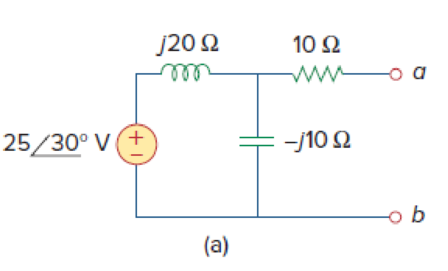
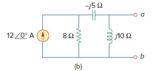
Figure 10.98
Expert Solution & Answer
Want to see the full answer?
Check out a sample textbook solution
Students have asked these similar questions
A source v. (t) =V cos 100xt has an internal impedance of (4 - j3)Q. 1f a purely
resistive load connected to this source has to extract the maximum power out of the
source, its value in Q should be
(A) 3
(B) 4
(C) 5
(D) 7
5. Analyze the following circuit, then,
a) find the voltage Vx
b) find the current at -j3 (ohm) capacitor
c) find the current at the 5(ohm) resistor
In any circuit if we have AC and DC sources, then circuit must be analyzed by superposition
Select one:
True
False
Chapter 10 Solutions
Fundamentals of Electric Circuits
Ch. 10.2 - Using nodal analysis, find v1 and v2 is in the...Ch. 10.2 - Calculate V1 and V2 in the circuit shown in Fig....Ch. 10.3 - Find Io in Fig. 10.8 using mesh analysis. Figure...Ch. 10.3 - Figure 10.11 For Practice Prob. 10.4. Calculate...Ch. 10.4 - Find current Io in the circuit of Fig. 10.8 using...Ch. 10.4 - Calculate vo in the circuit of Fig. 10.15 using...Ch. 10.6 - Determine the Norton equivalent of the circuit in...Ch. 10.7 - Find vo and io in the op amp circuit of Fig....Ch. 10.7 - Obtain the closed-loop gain and phase shift for...Ch. 10.8 - Use PSpice to obtain vo and io in the circuit of...
Ch. 10.8 - Obtain Vx and Ix in the circuit depicted in Fig....Ch. 10.9 - Determine the equivalent capacitance of the op amp...Ch. 10.9 - In the Wien-bridge oscillator circuit in Fig....Ch. 10 - The voltage Vo across the capacitor in Fig. 10.43...Ch. 10 - The value of the current Io in the circuit of Fig....Ch. 10 - Using nodal analysis, the value of Vo in the...Ch. 10 - In the circuit of Fig. 10.46, current i(t) is: (a)...Ch. 10 - Refer to the circuit in Fig. 10.47 and observe...Ch. 10 - For the circuit in Fig. 10.48, the Thevenin...Ch. 10 - In the circuit of Fig. 10.48, the Thevenin voltage...Ch. 10 - Refer to the circuit in Fig. 10.49. The Norton...Ch. 10 - Figure 10.49 For Review Questions 10.8 and 10.9....Ch. 10 - PSpice can handle a circuit with two independent...Ch. 10 - Determine i in the circuit of Fig. 10.50. Figure...Ch. 10 - Using Fig. 10.51, design a problem to help other...Ch. 10 - Determine vo in the circuit of Fig. 10.52. Figure...Ch. 10 - Compute vo(t) in the circuit of Fig. 10.53. Figure...Ch. 10 - Find io in the circuit of Fig. 10.54.Ch. 10 - Determine Vx in Fig. 10.55. Figure 10.55 For Prob....Ch. 10 - Use nodal analysis to find V in the circuit of...Ch. 10 - Use nodal analysis to find current io in the...Ch. 10 - Use nodal analysis to find vo in the circuit of...Ch. 10 - Use nodal analysis to find vo in the circuit of...Ch. 10 - Using nodal analysis, find io(t) in the circuit in...Ch. 10 - Using Fig. 10.61, design a problem to help other...Ch. 10 - Determine Vx in the circuit of Fig. 10.62 using...Ch. 10 - Calculate the voltage at nodes 1 and 2 in the...Ch. 10 - Solve for the current I in the circuit of Fig....Ch. 10 - Use nodal analysis to find Vx in the circuit shown...Ch. 10 - By nodal analysis, obtain current Io in the...Ch. 10 - Use nodal analysis to obtain Vo in the circuit of...Ch. 10 - Obtain Vo in Fig. 10.68 using nodal analysis.Ch. 10 - Refer to Fig. 10.69. If vs (t) = Vm sin t and vo...Ch. 10 - For each of the circuits in Fig. 10.70, find Vo/Vi...Ch. 10 - For the circuit in Fig. 10.71, determine Vo/Vs....Ch. 10 - Using nodal analysis obtain V in the circuit of...Ch. 10 - Design a problem to help other students better...Ch. 10 - Solve for io in Fig. 10.73 using mesh analysis....Ch. 10 - Use mesh analysis to find current io in the...Ch. 10 - Using mesh analysis, find I1 and I2 in the circuit...Ch. 10 - In the circuit of Fig. 10.76, determine the mesh...Ch. 10 - Using Fig. 10.77, design a problem help other...Ch. 10 - Use mesh analysis to find vo in the circuit of...Ch. 10 - Use mesh analysis to determine current Io in the...Ch. 10 - Determine Vo and Io in the circuit of Fig. 10.80...Ch. 10 - Compute I in Prob. 10.15 using mesh analysis....Ch. 10 - Use mesh analysis to find Io in Fig. 10.28 (for...Ch. 10 - Calculate Io in Fig. 10.30 (for Practice Prob....Ch. 10 - Compute Vo in the circuit of Fig. 10.81 using mesh...Ch. 10 - Use mesh analysis to find currents I1, I2, and I3...Ch. 10 - Using mesh analysis, obtain Io in the circuit...Ch. 10 - Find I1, I2, I3, and Ix in the circuit of Fig....Ch. 10 - Find io in the circuit shown in Fig. 10.85 using...Ch. 10 - Find vo for the circuit in Fig. 10.86, assuming...Ch. 10 - Using Fig. 10.87, design a problem to help other...Ch. 10 - Using the superposition principle, find ix in the...Ch. 10 - Use the superposition principle to obtain vx in...Ch. 10 - Use superposition to find i(t) in the circuit of...Ch. 10 - Solve for vo(t) in the circuit of Fig. 10.91 using...Ch. 10 - Determine io in the circuit of Fig. 10.92, using...Ch. 10 - Find io in the circuit of Fig. 10.93 using...Ch. 10 - Using source transformation, find i in the circuit...Ch. 10 - Using Fig. 10.95, design a problem to help other...Ch. 10 - Use source transformation to find Io in the...Ch. 10 - Use the concept of source transformation to find...Ch. 10 - Rework Prob. 10.7 using source transformation. Use...Ch. 10 - Find the Thevenin and Norton equivalent circuits...Ch. 10 - For each of the circuits in Fig. 10.99, obtain...Ch. 10 - Using Fig. 10.100, design a problem to help other...Ch. 10 - For the circuit depicted in Fig. 10.101, find the...Ch. 10 - Calculate the output impedance of the circuit...Ch. 10 - Find the Thevenin equivalent of the circuit in...Ch. 10 - Using Thevenins theorem, find vo in the circuit of...Ch. 10 - Obtain the Norton equivalent of the circuit...Ch. 10 - For the circuit shown in Fig. 10.107, find the...Ch. 10 - Using Fig. 10.108, design a problem to help other...Ch. 10 - At terminals a-b, obtain Thevenin and Norton...Ch. 10 - Find the Thevenin and Norton equivalent circuits...Ch. 10 - Find the Thevenin equivalent at terminals ab in...Ch. 10 - For the integrator shown in Fig. 10.112, obtain...Ch. 10 - Using Fig. 10.113, design a problem to help other...Ch. 10 - Find vo in the op amp circuit of Fig. 10.114....Ch. 10 - Compute io(t) in the op amp circuit in Fig. 10.115...Ch. 10 - If the input impedance is defined as Zin = Vs/Is,...Ch. 10 - Evaluate the voltage gain Av = Vo/Vs in the op amp...Ch. 10 - In the op amp circuit of Fig. 10.118, find the...Ch. 10 - Determine Vo and Io in the op amp circuit of Fig....Ch. 10 - Compute the closed-loop gain Vo/Vs for the op amp...Ch. 10 - Determine vo(t) in the op amp circuit in Fig....Ch. 10 - For the op amp circuit in Fig. 10.122, obtain Vo....Ch. 10 - Obtain vo(t) for the op amp circuit in Fig. 10.123...Ch. 10 - Use PSpice or MultiSim to determine Vo in the...Ch. 10 - Solve Prob. 10.19 using PSpice or MultiSim. Obtain...Ch. 10 - Use PSpice or MultiSim to find vo(t) in the...Ch. 10 - Obtain Vo in the circuit of Fig. 10.126 using...Ch. 10 - Using Fig. 10.127, design a problem to help other...Ch. 10 - Use PSpice or MultiSim to find V1, V2, and V3 in...Ch. 10 - Determine V1, V2, and V3 in the circuit of Fig....Ch. 10 - Use PSpice or MultiSim to find vo and io in the...Ch. 10 - The op amp circuit in Fig. 10.131 is called an...Ch. 10 - Figure 10.132 shows a Wien-bridge network. Show...Ch. 10 - Consider the oscillator in Fig. 10.133. (a)...Ch. 10 - The oscillator circuit in Fig. 10.134 uses an...Ch. 10 - Figure 10.135 shows a Colpitts oscillator. Show...Ch. 10 - Design a Colpitts oscillator that will operate at...Ch. 10 - Figure 10.136 shows a Hartley oscillator. Show...Ch. 10 - Refer to the oscillator in Fig. 10.137. (a) Show...
Additional Engineering Textbook Solutions
Find more solutions based on key concepts
The voltage source of the circuit shown in Fig. P1.29 is given by s(t)=25cos(4104t45)(V). Obtain an expression ...
Fundamentals of Applied Electromagnetics (7th Edition)
How many coulombs do 93.8 1016 electrons represent?
Principles Of Electric Circuits
Identify the type of input and output configuration for each diff-amp in Figure 18-35.
Electronics Fundamentals: Circuits, Devices & Applications
A constant voltage of 10V is applied to a 50H inductance, as shown in Figure P3.51 Figure P3 51 The current in ...
Electrical Engineering: Principles & Applications (7th Edition)
What is the color code for a 365- five-band precision resistor with a tolerance of 5 percent?
ELECTRICITY FOR TRADES (LOOSELEAF)
Find I0 and I1 in the circuit in Fig.P2.12.
Basic Engineering Circuit Analysis
Knowledge Booster


Learn more about
Need a deep-dive on the concept behind this application? Look no further. Learn more about this topic, electrical-engineering and related others by exploring similar questions and additional content below.Similar questions
- Convert the computed TEC into NEC. THEVENIN'S EQUIVALENT CIRCUIT (TEC) VTH RTH R3 (Load) NORTON'S EQUIVALENT CIRCUIT (NEC) IN RN R3 (Load)arrow_forwardThe super node additional equation in relation to the dependent voltage source is: 0.003 va 20 V 200 mA 04r, 100 O 3250 (). 500 O 200 () Ref Select one:arrow_forwardZVO A VM ll l Ciassroo docs.google.com a Q1 For the following circuit diagram, 1 is .......... 50 15 V 12V 40 50 I2 70 60 90 12 a 4 A 1 O -1 احمد عصام احمد 8:00- äc lul 21.04.20 O Darrow_forward
- Solve V, and V2. Also solve for the value of the current flowing through the j5 ohm inductor. Use Nodal Analysis. If the circuit diagram below is not loading, please refer to this attached file: Nodal Analysis Circuit Diagram-1.pdf 100,/60 V V2 42 V j5 0 -j9 N 20arrow_forward5- For the following circuit, determine l, Is., and V4 R, 320W R, Rz 400W R 20V 200w 200Warrow_forwardConsider the following circuit. It contains two independent sources and one dependent source. Using the superposition method, let us derive the output voltage V. 1ΚΩΣ IV ΙΚΩΣ 1 R₁ 2 V Find the Norton equivalent of the circuit. +1 10092 R₂ www R3 vo ΙΚΩΣ www RA |arrow_forward
- Electrical Engineering Determine the current Io using mesh analysis UTM UT j2 n StM UTM 5 UTM 420° UTM 25290° V mh UTM UTM UM 1520° A 2UTM UTSUTM UM - j4n TM I3 10Ω M UTM I4arrow_forwardIn the given figure, a) find the voltages at node 1,2,3,& 4 b) also, find the voltage drop across each resitancearrow_forward0198% 10:15 Leila Hammadi B... 1 minute ago Given the following circuit with Is=40<30° mA Is 12:1 V 10002 Select one: O a. V, 120<60° V b. V,-480<30° V C. None of these d. V,-480<-30° V < O Oarrow_forward
- asaparrow_forwardConsider the circuit given, where R= 3 . Hic 48 2 + 10u(-t) mA 2 mF : 250 mH Determine id0¯). (You must provide an answer before moving on to the next part.) The value of ido") is A. elllarrow_forwardAssume that the value of RL is such that maximum power is transferred to it. VT= -18V, RT= 9.52 find the value of RL the power PL dissipated by RLarrow_forward
arrow_back_ios
SEE MORE QUESTIONS
arrow_forward_ios
Recommended textbooks for you
 Delmar's Standard Textbook Of ElectricityElectrical EngineeringISBN:9781337900348Author:Stephen L. HermanPublisher:Cengage Learning
Delmar's Standard Textbook Of Electricity
Electrical Engineering
ISBN:9781337900348
Author:Stephen L. Herman
Publisher:Cengage Learning
Lesson 2 - Source Transformations, Part 2 (Engineering Circuits); Author: Math and Science;https://www.youtube.com/watch?v=7gno74RhVGQ;License: Standard Youtube License