
Applied Statics and Strength of Materials (6th Edition)
6th Edition
ISBN: 9780133840544
Author: George F. Limbrunner, Craig D'Allaird, Leonard Spiegel
Publisher: PEARSON
expand_more
expand_more
format_list_bulleted
Videos
Textbook Question
Chapter 10, Problem 10.12P
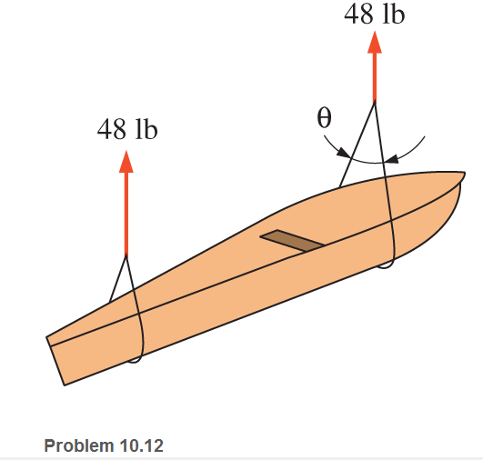
A concrete canoe in storage is supported by two rope slings, as shown. Each sling supports 48 Ib. The rope has a tensile breaking strength of 252 lb. Determine the maximum value of θ if there is to be a factor of safety of 4.0 against breaking.
Expert Solution & Answer
Want to see the full answer?
Check out a sample textbook solution
Students have asked these similar questions
If load P = 22.1 kips, determine the normal force in bar (1).
If load P = 17.3 kips, determine the normal force in bar (1).
A
6 ft
36.5 kips
28.8 kips
17.7 kips
O 34.3 kips
O 31.4 kips
D
B
(1)
4 ft
If load P = 22.9 kips, determine the normal
force in bar (1).
D
P
A
6 ft
51.9 kips
44.8 kips
27.3 kips
38.2 kips
O 40.4 kips
B
(1)
4 ft
Chapter 10 Solutions
Applied Statics and Strength of Materials (6th Edition)
Ch. 10 - A 916 - in. - diameter steel rod is tested in...Ch. 10 - A concrete cylinder 150 mm in diameter was tested...Ch. 10 - Prob. 10.3PCh. 10 - The data from the tension test of a steel specimen...Ch. 10 - An 18-in.-long titanium alloy rod is subjected to...Ch. 10 - ASTM A36 steel rods are used to support a balcony....Ch. 10 - A 450-mm-long AISI 1020 steel rod is subjected to...Ch. 10 - A tension member in a roof truss is composed of...Ch. 10 - A short, solid, compression member of circular...Ch. 10 - A main cable in a large bridge is designed for a...
Ch. 10 - Test results of a steel specimen indicated an...Ch. 10 - A concrete canoe in storage is supported by two...Ch. 10 - A load is applied to a rigid bar that is...Ch. 10 - Prob. 10.14CPCh. 10 - Write a program that will allow a user to input...Ch. 10 - A 12 - in. - diaiíct.cr structural nickel steel...Ch. 10 - Compute the modulus of elasticity of a copper...Ch. 10 - A concrete cylinder 6 in. in diameter was tested...Ch. 10 - An aluminum bar 2 in. by 12 - in. in cross section...Ch. 10 - During a tensile test of a steel specimen, the...Ch. 10 - A 12.5-mm-diameter steel rod was subjected to a...Ch. 10 - Prob. 10.22SPCh. 10 - A standard steel specimen having a diameter of...Ch. 10 - 10.24 A tension member in a structure is composed...Ch. 10 - A pair of wire cutters is designed to operate...Ch. 10 - Calculate the end bearing length required for a...Ch. 10 - Design a 3-m-long rod subjected to a tensile load...Ch. 10 - The collar bearing shown is subjected to a...Ch. 10 - A 10-ft-long steel member is subjected to a...Ch. 10 - Two steel bars A and B support a load P, as shown....Ch. 10 - Prob. 10.31SP
Knowledge Booster


Learn more about
Need a deep-dive on the concept behind this application? Look no further. Learn more about this topic, mechanical-engineering and related others by exploring similar questions and additional content below.Similar questions
- A 5-kN tensile load is applied to a test coupon made from 1.6-mm flat steel plate (E = 200 GPa, v = 0.30). Determine the change in volume of the 50-mm gage length segment AB by computing the dilatation of the material.arrow_forwardA bar, 12 mm in diameter is acted upon by an axial load of 20 kN. The change in diameter is measured as 0.03 mm. DeterminePoisson’s ratioYoung’s modulusBulk modulus Assume modulus of rigidity as 80 GPaarrow_forwardTwo solid cylindrical rods support a load of P = 17 kN as shown. Determine the axial load in rod (1).arrow_forward
- Consider the wooden member subjected to a tensile load P = 11.0 kN. Determine the magnitude of the normal force at the inclined section shown.arrow_forwardQuestion 4: A stepped circular bar having diameters of 20 mm, 15 mm, and 10 mm over axial lengths of 100 mm, 80 mm and 60 mm is subjected to an axial tensile force of 5 kN If E= 100 GPa and v= 0.32 for the material of the bar determine: A. Total change in length. B. Change in each diameter.arrow_forwardA straight girder of uniform section and length L rests on supports at the ends, and is propped up by a third support in the middle. The weight of the girder and its load is w per unit length. If the central support does not yield, prove that it takes a load equal to (5/8)wL. ANSWER: 1.80cm and 2.48cm Please show solution to the answer.arrow_forward
- Axial loads are applied with rigid bearing plates to the solid cylindrical rods shown. If F₁ = 33 kips, F₂ = 18 kips, F3 = 25 kips, and F4 = 38 kips, determine the absolute value of the axial load in rod (2). F₁ A F₂ (1) F₂ B F3 (3) F3 F₁ с D O 21 kips 16 kips 29 kips 25 kips O 19 kipsarrow_forwardA compression member of 2-m effective length consists of a solid 30-mm- diameter brass rod. In order to reduce the weight of the member by 25%, the solid rod is replaced by a hollow rod of the cross section shown. 30 mm 15 mm 30 mmarrow_forwardAxial loads are applied with rigid bearing plates to the solid cylindrical rods shown. If F₁ = 31 kips, F₂ = 11 kips, F3 = 22 kips, and F4 = 36 kips, determine the absolute value of the axial load in rod (2). F A F₂ (1) F₂ B F3 C (3) D O 16 kips O 12 kips O 7 kips O 9 kips O 22 kipsarrow_forward
- A column of intermediate length buckles when the compressive stress is 40 ksi. If the slenderness ratio is 60, determine the tangent modulus.arrow_forwardIf the base plate carries a load of XX kN (including self-weight, which is equally distributed on the four corners), calculate the stress on the lower washers before the nuts are tightened. Analyse the stress in the upper and lower washers, when the nuts are tightened so as to produce a tension of YY kN on each bolt. Please refer appendix for XX and YY values. Xx=145kN Уу350kN 44 mm- Upper washer Base plate Lower washer - 20 mm 22 mm 50 mmarrow_forwardDetermine the equivalent stiffness constant of the ff.arrow_forward
arrow_back_ios
SEE MORE QUESTIONS
arrow_forward_ios
Recommended textbooks for you
 Elements Of ElectromagneticsMechanical EngineeringISBN:9780190698614Author:Sadiku, Matthew N. O.Publisher:Oxford University Press
 Mechanics of Materials (10th Edition)Mechanical EngineeringISBN:9780134319650Author:Russell C. HibbelerPublisher:PEARSON
 Thermodynamics: An Engineering ApproachMechanical EngineeringISBN:9781259822674Author:Yunus A. Cengel Dr., Michael A. BolesPublisher:McGraw-Hill Education
 Control Systems EngineeringMechanical EngineeringISBN:9781118170519Author:Norman S. NisePublisher:WILEY
 Mechanics of Materials (MindTap Course List)Mechanical EngineeringISBN:9781337093347Author:Barry J. Goodno, James M. GerePublisher:Cengage Learning
 Engineering Mechanics: StaticsMechanical EngineeringISBN:9781118807330Author:James L. Meriam, L. G. Kraige, J. N. BoltonPublisher:WILEY
Elements Of Electromagnetics
Mechanical Engineering
ISBN:9780190698614
Author:Sadiku, Matthew N. O.
Publisher:Oxford University Press
Mechanics of Materials (10th Edition)
Mechanical Engineering
ISBN:9780134319650
Author:Russell C. Hibbeler
Publisher:PEARSON
Thermodynamics: An Engineering Approach
Mechanical Engineering
ISBN:9781259822674
Author:Yunus A. Cengel Dr., Michael A. Boles
Publisher:McGraw-Hill Education
Control Systems Engineering
Mechanical Engineering
ISBN:9781118170519
Author:Norman S. Nise
Publisher:WILEY
Mechanics of Materials (MindTap Course List)
Mechanical Engineering
ISBN:9781337093347
Author:Barry J. Goodno, James M. Gere
Publisher:Cengage Learning
Engineering Mechanics: Statics
Mechanical Engineering
ISBN:9781118807330
Author:James L. Meriam, L. G. Kraige, J. N. Bolton
Publisher:WILEY
Differences between Temporary Joining and Permanent Joining.; Author: Academic Gain Tutorials;https://www.youtube.com/watch?v=PTr8QZhgXyg;License: Standard Youtube License