
Concept explainers
Videos
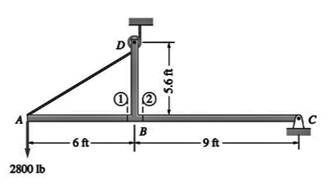
The structure is supported by a pin at C and a cable attached to A. The cable runs over the small pulley D. Find the internal force systems acting on sections 1 and 2.
Internal force system acting on section 1 and 2
Answer to Problem 6.15P
The horizontal force
The vertical force
The bending moment
The horizontal force
The vertical force
The bending moment
Explanation of Solution
Given information:
If all external forces are known, we can use equilibrium analysis to find internal forces.
Steps to follow in the equilibrium analysis of a body are:
1. Draw the free body diagram.
2. Write the equilibrium equations.
3. Solve the equations for the unknowns.
Calculation:
FBD of entire body
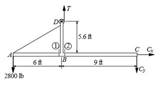
Assume
For the equilibrium of entire section, the bending moment about point C is equal to zero.
FBD of section 1
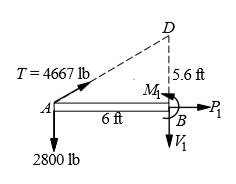
Assume
For the equilibrium of section AB, the bending moment about point B is equal to zero.
Write equilibrium equation in horizontal direction.
Write equilibrium equation in vertical direction.
FBD of section 2
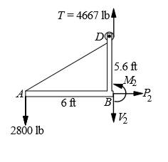
Assume
For the equilibrium of section AB, the bending moment about point B is equal to zero.
Write equilibrium equation in horizontal direction.
Write equilibrium equation in vertical direction.
Conclusion:
The horizontal force
The vertical force
The bending moment
The horizontal force
The vertical force
The bending moment
Want to see more full solutions like this?
Chapter 6 Solutions
International Edition---engineering Mechanics: Statics, 4th Edition


- The 1800lbin. couple is applied to member DEF of the pin-connected frame. Find the internal force systems acting on sections 1 and 2.arrow_forwardFind the internal force systems acting on sections 1 and 2.arrow_forwardThe cable supports three 400-lb loads as shown. If the maximum allowable tension in the cable is 900 lb, find the smallest possible sag hC at C.arrow_forward
- Determine A·(B×C) The light boom AB is attached to a vertical wall by a ball and socket joint at A and supported by two cables at B. A force P is applied at B where P = 11i - 10j kN.Note that the reaction force at A acts along the boom because it is a two-force member. Calculate the magnitude of the reaction force at A in kN Determine the magnitude of the moment of P about the origin (point O) in Nm.arrow_forwardFind the reaction at A due to the uniform loading and the applied couple. The force reaction is positive if upward, negative if downward. The moment reaction is positive if counterclockwise, negative if clockwise.arrow_forwardDraw the FBD. Find the support reactions in A and tension force in the cable. P = 8 KN.arrow_forward
- Solve the components of force at B along ABC beamarrow_forwardW2 acts at the center G of the bar. Find the cables' tensions and the reactions at ball and socket O. W1 is 515 N. W2 is 190 N.arrow_forwardThe cable carrying 60-lb loads at B and C is held in the position shown by the horizontal force P = 80 lb applied at A. Determine the following: Determine the force in segment BC. Determine the force in segment CD. Determine the value of h. Determine the smallest measure of angle ?BCx segment BC makes with the horizontal. Determine the smallest measure of angle ?CDx segment CD makes with the horizontal.arrow_forward
 International Edition---engineering Mechanics: St...Mechanical EngineeringISBN:9781305501607Author:Andrew Pytel And Jaan KiusalaasPublisher:CENGAGE L