
Applied Statics and Strength of Materials (6th Edition)
6th Edition
ISBN: 9780133840544
Author: George F. Limbrunner, Craig D'Allaird, Leonard Spiegel
Publisher: PEARSON
expand_more
expand_more
format_list_bulleted
Concept explainers
Videos
Textbook Question
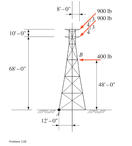
Chapter 3, Problem 3.58SP
The transmission tower shown is subjected to a horizontal wind force of 400 lb acting at point B. Support cables transmit a force of 90 lb at two different levels acting as shown. Calculate the moment about point A at the base of the tower.
Expert Solution & Answer

Learn your wayIncludes step-by-step video

schedule07:07
Students have asked these similar questions
The crowbar is subjected to a vertical force of P = 27 lb at the grip, whereas it takes a force of F = 160 lb at the claw to pull the nail out. The crowbar contacts the board at point A.
Find the moment of the force P about point A and the moment of the force F about point A.
The transmission tower shown is subjected to a horizontal wind force of 90N acting at point B.
Supported cables transmit a force of 200N at two different levels acting as shown. Calculate the
resultant moment about point A at the base of the tower.
3m
20m
3.5m
2.5m
A
B
200N
200N
90N
15m
The tire wrench shown in the accompanying figure is used to tighten the bolt on a
wheel. Given the information on the diagram, determine the moment about point
O for the two loading situations shown:
a. pushing perpendicular to the wrench arm, and
b. pushing at a 75° angle, as shown.
Chapter 3 Solutions
Applied Statics and Strength of Materials (6th Edition)
Ch. 3 - through 3.3 Determine the magnitude, direction,...Ch. 3 - Determine the magnitude, direction, and sense of...Ch. 3 - Determine the magnitude, direction, and sense of...Ch. 3 - Solve Problem 3.1 through 3.3 using the method of...Ch. 3 - Solve Problem 3.1 through 3.3 using the method of...Ch. 3 - through 3.6 Solve Problem 3.1 through 3.3 using...Ch. 3 - The 150-lb force shown is the resultant of two...Ch. 3 - Find the resultant force P exerted on the tree.Ch. 3 - Find the resultant force R exerted on the pole.Ch. 3 - Calculate the resultant force on the screw eye....
Ch. 3 - Determine the resultant of the coplanar concurrent...Ch. 3 - Use the parallelogram law to find the following...Ch. 3 - Prob. 3.13PCh. 3 - Determine the resultant of the coplanar concurrent...Ch. 3 - The resultant of the concurrent force system shown...Ch. 3 - Three force of 900 lb, 1000 lb, and 600 lb are...Ch. 3 - The four forces shown hade parallel lines of...Ch. 3 - Three coplanar concurrent forces act as shown. a....Ch. 3 - Four coplanar concurrent forces act as shown a....Ch. 3 - Determine the resultant of the four forces of...Ch. 3 - For the concrete wall and footing shown: a....Ch. 3 - Calculate the moment of the 550-lb force about...Ch. 3 - In Problem 3.22 , calculate the moment about point...Ch. 3 - Compute the moment about point A for the linkage...Ch. 3 - Compute the moment of the force F about point A...Ch. 3 - Determine the magnitude of the resultant of the...Ch. 3 - Determine the magnitude of the resultant of the...Ch. 3 - Determine the magnitude of the resultant of the...Ch. 3 - Determine the magnitude of the resultant of the...Ch. 3 - Determine the resultant and its location for the...Ch. 3 - Compute the magnitude, sense, and location of the...Ch. 3 - Compute the magnitude, sense, and location of the...Ch. 3 - Compute the magnitude and location of the...Ch. 3 - Determine the magnitude and location of the...Ch. 3 - Fresh water is impounded behind a dam to a height...Ch. 3 - Determine the magnitude and location of the...Ch. 3 - Determine the magnitude and location of the...Ch. 3 - Compute the magnitude and direction of the...Ch. 3 - Compute the magnitude and direction of the...Ch. 3 - Compute the magnitude and direction of the...Ch. 3 - A body is subjected to the following three...Ch. 3 - Determine the magnitude, direction, and sense of...Ch. 3 - Determine the magnitude, direction, and sense of...Ch. 3 - Determine the resultant of the load system shown....Ch. 3 - For the concrete structure shown, determine the...Ch. 3 - For the following computer problems, any...Ch. 3 - For the following computer problems, any...Ch. 3 - For the following computer problems, any...Ch. 3 - 3.49 Determine the magnitude, direction, and sense...Ch. 3 - The resultant and one-component force of a...Ch. 3 - The resultant force of a concurrent force system...Ch. 3 - Determine the magnitudes of forces P1 and P2 such...Ch. 3 - The resultant force of a concurrent force system...Ch. 3 - A hockey puck is acted on simultaneously by two...Ch. 3 - Determine the resultant force for each of the...Ch. 3 - Determine the resultant force for each of the...Ch. 3 - The resultant of the three concurrent forces shown...Ch. 3 - The transmission tower shown is subjected to a...Ch. 3 - A gravity-type masonry dam, as shown, depends on...Ch. 3 - The transfomer (as shown) must be lifted...Ch. 3 - Refer to the diagram for Problem 3.60 /. Assume...Ch. 3 - The plastic barrel tent anchor of Problem 2.11...Ch. 3 - Calculate the moment of the forces shown with...Ch. 3 - Determine the magnitude and location of the...Ch. 3 - Determine the moment (about point A) of the appied...Ch. 3 - The lift force on the wing of an aircraft is...Ch. 3 - A beam is subjected to distributed loads as shown....Ch. 3 - For the concrete gravity wall shown, determine the...Ch. 3 - Fresh water is impounded to a height of 8 ft...Ch. 3 - Plank, 2 in. by 10 in. in cross section and 5 ft...Ch. 3 - a. Compute the moment (about point A) of the...Ch. 3 - Determine the resultant of the three forces acting...Ch. 3 - a. Calculate the moments about points A and B due...Ch. 3 - Determine the magnitude of F1 and F2 shown such...Ch. 3 - Calculate the magnitude, direction, and sense of...
Additional Engineering Textbook Solutions
Find more solutions based on key concepts
14. When one tries to stop a car, both the reaction time of the driver and the braking time must be considered....
Thinking Like an Engineer: An Active Learning Approach (4th Edition)
What parts are included in the vehicle chassis?
Automotive Technology: Principles, Diagnosis, and Service (5th Edition)
The rigid beam supports the load of 60 kN. Determine the displacement at B. Take E = 60 GPa, and ABC = 2 (10-3)...
Mechanics of Materials
Determine the support reactions at the rigid supports A and C. The material has a modulus of elasticity of E.
Mechanics of Materials (10th Edition)
The magnitude of resultant force FR acting on the screw eye and its direction θ measured clockwise from the x a...
Engineering Mechanics: Statics & Dynamics (14th Edition)
Determine the tension developed in each cable for equilibrium of the 300-lb crate.
Engineering Mechanics: Statics
Knowledge Booster


Learn more about
Need a deep-dive on the concept behind this application? Look no further. Learn more about this topic, mechanical-engineering and related others by exploring similar questions and additional content below.Similar questions
- Determine the moment of the force F about point A in terms of F and d. Use (a) the scalar method; and (b) the vector method.arrow_forwardElements of the lower arm are shown in the figure. The weight of the forearm is 6.5 Ib with mass center at G. Determine the combined moment about the elbow pivot O of the weights of the forearm and the sphere. What must the biceps tension force be so that the overall moment about O is zero? The moment is positive if counterclockwise, negative if clockwise.arrow_forwardThe blades of the portable fan generate a 1.0-lb thrust T as shown. Compute the moment Mo of this force about the rear support point O. For comparison, determine the moment about O due to the weight of the motor-fan unit AB, whose weight of 7.7 lb acts at G. The moments are positive if counterclockwise, negative if clockwise. Assume a = 9.0 in., b = 1.5 in., c = 12.5 in., d = 3.5in., e = 2.5 in., and 0 = 16⁰. Air flow B d C 0arrow_forward
- The blades of the portable fan generate a 1.0-lb thrust T as shown. Compute the moment Mo of this force about the rear support point O. For comparison, determine the moment about O due to the weight of the motor-fan unit AB, whose weight of 7.7 lb acts at G. The moments are positive if counterclockwise, negative if clockwise. Assume a = 9.0 in., b = 1.5 in., c= 12.5 in., d = 3.5in., e = 2.5 in., and 0 = 16% Air flow Answers: Due to thrust T Mo= Due to weight Mo= B 15.574 i -22.626 lb-in. Ib-in.arrow_forwardConsider the system shown in figure. Determine the moment of the force F about the door hinge at A.arrow_forwardDetermine the moment of the force about point A as shown in the Figure below.arrow_forward
- The roof is supported by the bracket at O and by two cables as shown in the Fig. below. If the cables exert forces FAB = 100 N and FAC = 120 N on the wall hook at A as shown in Fig.; Determine the moment about O (the origin) of the forces exerted by the cables at B and C.arrow_forwardFind the equivalent force and moment of the system at O.arrow_forwardSample Problem 2/5 Calculate the magnitude of the moment about the base point O of the 600-N force 2 m 40 40° 50 600N 4 m 600 N 77TTTTarrow_forward
- The system below is to be converted to a single force P and a single moment B at point M.Draw the equivalent system and find the magnitude and direction of P and M if θ is 25°.Each unit in the grid is 1 m.arrow_forwardFind the moment about point A resulting from the force of the knee on the helmet, as shown. Also, find the force F at the base of the neck needed to resist this moment.arrow_forwardThe port hull of a catamaran (top view shown) has cleats at points A, B, and C. A rope having 100N force is to be attached to one of these cleats. If the force is to produce the largest possible counterclockwise moment about point O, determine the cleat to which the rope should be attached and the direction the rope should be pulled (measured positive counterclockwise from the positive x direction). Also, determine the value of MO produced. Assume all cleats, point O, and the rope lie in the same plane.arrow_forward
arrow_back_ios
SEE MORE QUESTIONS
arrow_forward_ios
Recommended textbooks for you
 International Edition---engineering Mechanics: St...Mechanical EngineeringISBN:9781305501607Author:Andrew Pytel And Jaan KiusalaasPublisher:CENGAGE L
International Edition---engineering Mechanics: St...
Mechanical Engineering
ISBN:9781305501607
Author:Andrew Pytel And Jaan Kiusalaas
Publisher:CENGAGE L
Introduction To Engg Mechanics - Newton's Laws of motion - Kinetics - Kinematics; Author: EzEd Channel;https://www.youtube.com/watch?v=ksmsp9OzAsI;License: Standard YouTube License, CC-BY