
Videos
(a) Obtain y, z, h, and t parameters for the network shown in Fig. 16.67 using either the defining equations or mesh/nodal equations. (b) Verify your answers using the relationships in Table 16.1.
(a)
The
Answer to Problem 59E
The
Explanation of Solution
Given data:
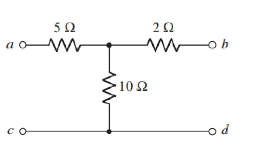
The given diagram is shown in Figure 1.
Calculation:
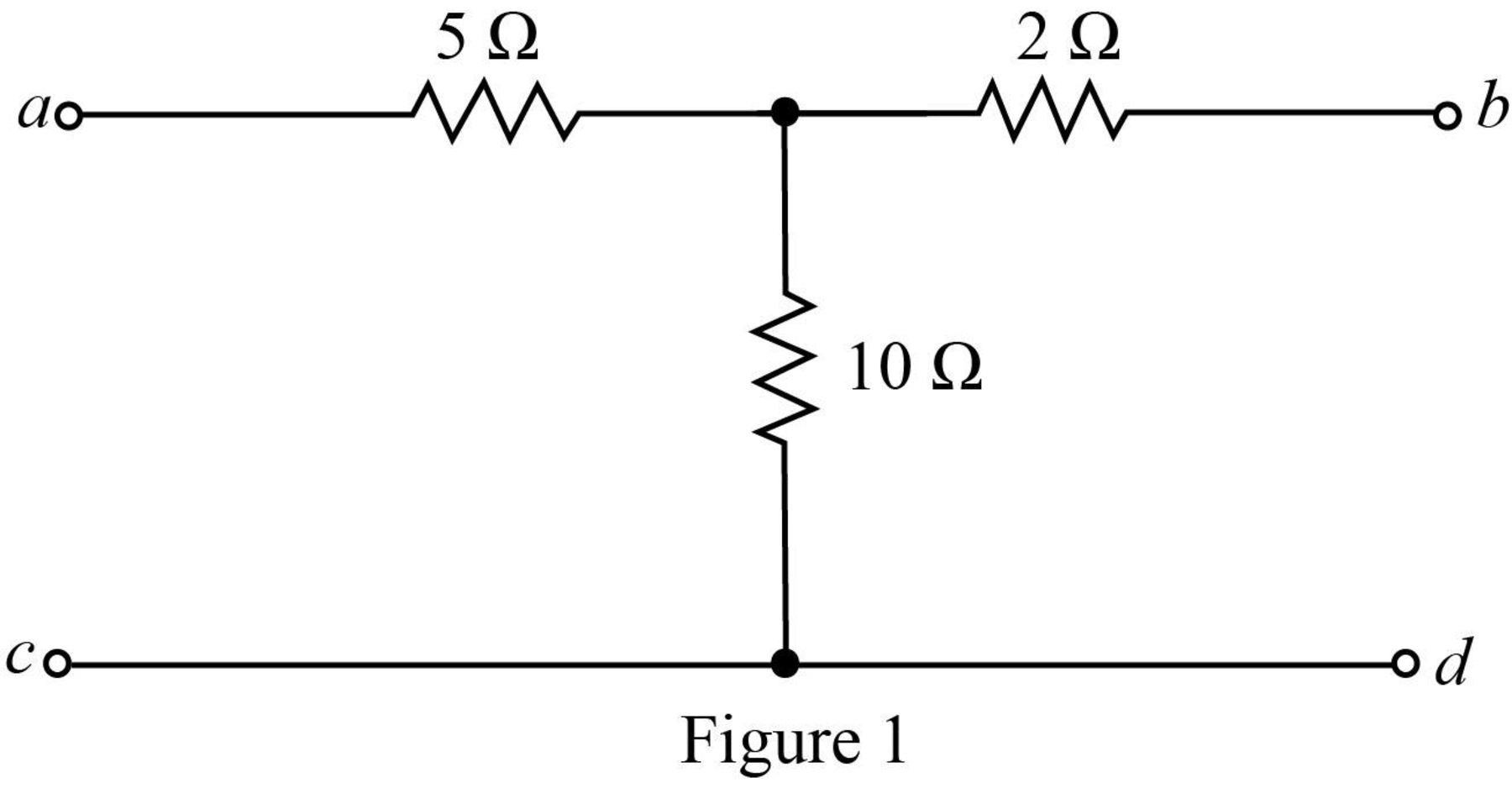
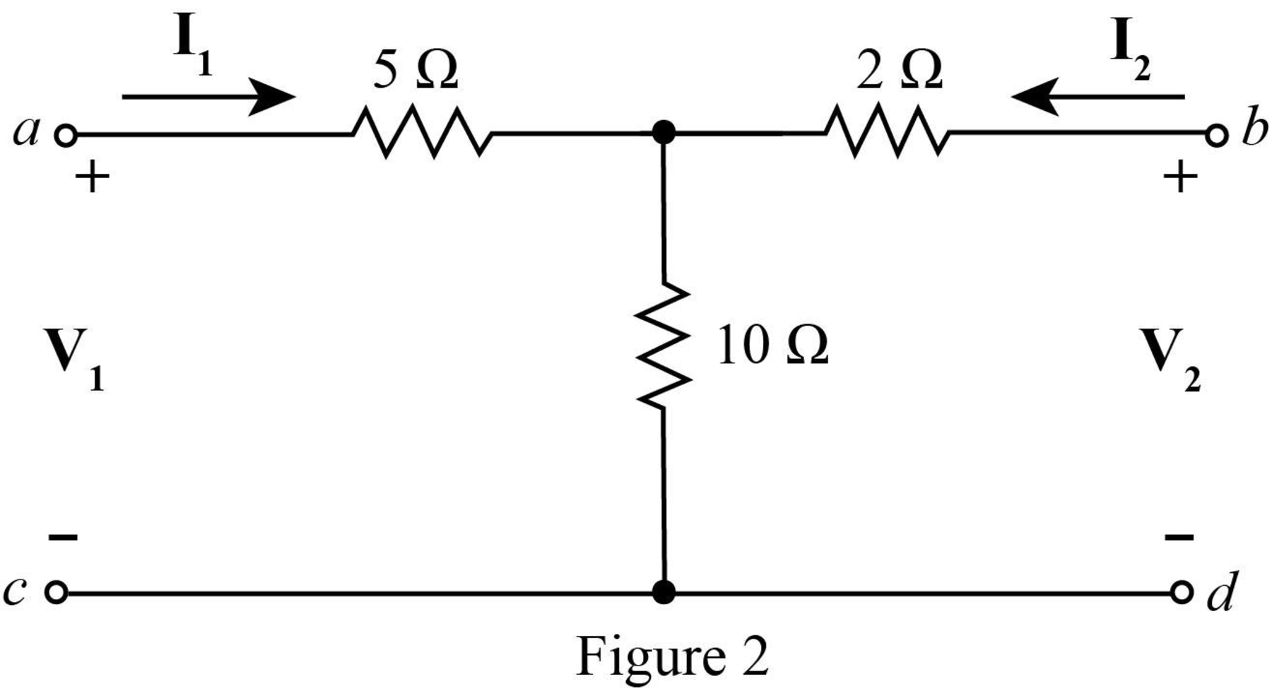
Mark the branch currents and open circuit voltages.
The required diagram is shown in Figure 2.
Apply KVL at the input side.
Apply KVL at the output side.
The standard equations for
Compare equation (1) with equation (3).
Compare equation (2) with equation (4).
The
Substitute
Rearrange equation (1) as,
Rearrange equation (2) as,
Substitute
Substitute
The standard equations for
Compare equation (7) with equation (9).
Compare equation (8) with equation (10).
The
Substitute
Substitute
The standard equations for
Compare equation (11) with equation (12).
Compare equation (6) with equation (13).
The
Substitute
Rearrange equation (6) as,
Substitute
The standard equations for
Compare equation (15) with equation (16).
Compare equation (14) with equation (17).
The
Substitute
Conclusion:
Therefore, the
(b)
To verify: The value of
Explanation of Solution
Calculation:
The relation between
The determinant
Substitute
The relation between
Substitute
The relation between
Substitute
Conclusion:
Thus, within the limits of error the value of
Want to see more full solutions like this?
Chapter 16 Solutions
Loose Leaf for Engineering Circuit Analysis Format: Loose-leaf
Additional Engineering Textbook Solutions
Electric machinery fundamentals
Principles and Applications of Electrical Engineering
Introductory Circuit Analysis (13th Edition)
Principles Of Electric Circuits
Fundamentals of Applied Electromagnetics (7th Edition)
Fundamentals of Electric Circuits


- 1 Construct a table similar to Table 16.2 for a 4-bit A/D converter if Va = 5 V with a reference voltage of 16 V. Analog input VI Clock Vo Sample-and-hold + FUL Va Vb 4-bit SAR 4-bit DAC 4-bit register Logic control Ring counter (a) 4-bit A/D converter MSB B3 B₂ B₁ Bo LSB Outputarrow_forwardQ4. Use a Karnaugh map to minimize the following standard SOP expression: (15 M) ABC + ABC + ABC + ABC + ABC Q5. Plot the corresponding SUM and CARRY outputs of half-adder circuit, for the given A and B inputs. And give the logical expression for both. (15 M) HA A Barrow_forwardB3 Determine the Y -bus matrix for the given Fig. -j 1.5 -j 3 -j 2 -j 2.5 -j 3.5 3 -j 1.5 4arrow_forward
- For a set of linear algebraic equations in matrix format, Axy, for a unique solution to exist, det(A) should be __________.arrow_forward250 Zo 1000 Zo 500 250 [S11 S12 S = [S21 S22] Find the S matrix of the given configuration? Zo=50 ohm.arrow_forwardPractice: || Find Io in the following circuit using the concept of source transformation, 16.7 Jjarrow_forward
- A combinational circuit has four inputs (A,B,C,D) and three outputs (X.Y,Z). XYZ represents a binary number whose value equals the number of 1's at the input. For example if ABCD=1011, XYZ=011.(a) find the minterm expansions for X,Y, and Z.(b) find the maxterm expansions for Y and Z.arrow_forward6) A combinational circuit has four inputs (A,B,C,D) and three outputs (X,Y,Z). XYZ represents a binary number whose value equals the number of 1's at the input. For example if ABCD = 1011 then xyz = 011. a. Find the minterm expansions for X,Y and Z. b. Find the maxterm expansions for X,Y and Z.arrow_forwardUse Node-Voltage Method to find the voltage v_1. V, 20 40 V 202 800 24.75 V Select one: O a. 24.75 v O b. None of them O c. 28 v O d. 40 v O e. 30 varrow_forward
- 16.8 Find the Z parameters for the two-port network in Fig. P16.8. I1 21 N I2 V1 42 0 10.5 V2 Figure P16.8arrow_forwardQ4. Use a Karnaugh map to minimize the following standard SOP expression: (15 M) ABC + ABC + ABC + ABC + ABC Q5. Plot the corresponding SUM and CARRY outputs of half-adder circuit, for the given A and B inputs. And give the logical expression for both.(15 M) +H Barrow_forwardIn a 3 - variable K-Map, the diagonal cells are not adjacent Select one: O True Falsearrow_forward
 Power System Analysis and Design (MindTap Course ...Electrical EngineeringISBN:9781305632134Author:J. Duncan Glover, Thomas Overbye, Mulukutla S. SarmaPublisher:Cengage Learning