
Videos
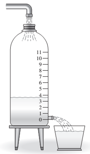
Consider the milk container of Example 1.4.2 (Figure 1.4.7). A straw 19 cm long was inserted in the side of the container. While adjusting the tap flow to keep the water height constant, the time for the outflow to fill a 250-ml cup was measured. This was repeated for several heights. The data are given in the following table.
Obtain a functional description of the volume outflow rate f through the straw as a function of water height h above the hole.
Figure 1.4.7 An experiment to determine flow rate versus liquid height.
Want to see the full answer?
Check out a sample textbook solution
Chapter 1 Solutions
System Dynamics


- upper leg muscle 9 cm in radius). 2) Don't ever try the acorn diet, its nuts. In the tree diagrammed here, a force of 800 N is exerted at the tip of the limb (equivalent to the weight of "800 apples). The limb is circular in cross-section and 2 m long with a tip radius of 3 cm a base radius of 10 cm. The radius increases linearly from the tip to the base. Plot the tensile stress at the top of the limb along its length. Where along the length would you expect the limb to break? M. X. Lo Yarrow_forwardPROPAGATION OF ERROR You are tasked to supervise the design of 0.5MW wind turbine to be constructed in a Wind Farm in Pililla, Rizal. Suppose the design criteria are as follows: The air density as surveyed after 2 year period averaged at 1.225 kg / cubic meter. The sweeping diameter of the rotor blades is 125m, and the anemometer reading in the area amounts to 4.2m/s on a 2 year period of survey. What is the theoretical power output of the turbine assuming 100% efficiency of operation? Your answer must be in kW and in two decimal places with correct signs. In the previous problem, if the diameter measurement is off by 0.1m and the anemometer reading is also fluctuating by 0.05m/s and if the error measurement for theoretical power output must be limited to 3%, WHY OR WHY NOT should you accept the design? * Show complete solution in paper.arrow_forwardA physics lab Consist of a large bowl attached to wire. Students hold onto one of the wire the whirl the ball around in circles and count the number of rotations per second. One group finds these numbers: ball mass=320g, wire length=1.3m, number of rotations/second=2.5. The wire is made of steel with a diameter of 1mm and a Young’s modulus of 20x10^10 N/m^2. How much does the wire stretch due to the tension on it? Should the students correct their data for the wire stretching?arrow_forward
- 3G 9:.. %79 Final 1st attem... F2 У - ахis Fs F4 F1 х - ахis X- axis y - axis F3 F2 F1 Figure (1) Figure (2) 250 N 36.87 D F2 60° 0.5 m 1 m o! 0.2 m 1 m 300 NE F1 1 m Figure (3) Figure (4) Q1] Answer the following questions: For figure (1): The object is subjected to two forces F1 = 25 N, and F2 = 50 N. Set x = 30°, 0 = 45° , and ß = 30°. 1- What is the magnitude of the resultant of these two forces? a) 39.4 N b) 80.1N c) 41.6 N d) 69.8 N e) 71.4 N f) 46.1 N g) None of them 2 - What is the direction of the resultant force measured counterclockwise from the positive x-axis? а) 14.30 b) 392.6° c) 9.2° d) 322.9° e) 6.8° f) 344.2° g) None of them For figure (2): The arm in is subjected to five forces as follows: F1 = 135 N, F2 = 98 N, F3 = 210 N, F4 = 56 N. If the y – direction resultant force is 144 N, and x = 40°, 0 = 50°, B = 70°: 3 – What is the magnitude of the force F5? a) 318.4 N b) 99.1N c) 151.6 N d) 36.5 N e) 111.2 N f) 18.8 N g) None of them 4 - What is the magnitude of the…arrow_forwardThe left side of this equation tells how much energy Q the cylinder gives to the water while it cools. The right side of this equation tells how much energy Q the water and aluminum cup absorb from the cylinder to warm up. Because it is the same energy, they are equal. What is known in this equation? Mcyl 411.7 g, malum 46.5 g, malum+water = 175 g Can you find: mwater =? g Twater = Talum = 20°C (water and cup of room temperature) 90°C, T; = 35°C (hot cylinder and cool "cylinder+cup+water" temperatures) Tcyl kCal Calum = 0.22, Cwater 1 (specific heat of water and aluminum, measured in units kg-°C What are we looking for is Ccul - How we find it? Plug all the numbers into the equation (1), Ccul will be one unknown which you can calculate from the equation. Important, convert all the masses from grams to kilograms! After you find Ccyl, compare it to known value for the copper 0.093(our cylinder is made out of copper). |Ceyl -0.093| % : · 100% 0.093arrow_forwardPROBLEM #1: Complete the data of the table below. Copy the entire table in your paper and use a different colored pen for your answers, you may also box your answers. Show solution. T:K P: kPa H: kJ/kg U: kJ/kg State (if wet steam provides xv as well) 1 525 350 2 125 2700 3 455.15 750 4 600 Xv = 0.8 5 200 1800 PROBLEM #2 A nozzle is used to increase the velocity of steam before it enters a turbine as a part of a power plant. The steam entering is at 1 MPa, 500 K and leaves at the conditions of 350°C and 2 MPa. If the nozzle has an inlet diameter of 3 cm and an outlet diameter of 1 cm, how much is transferred during the process? Is it lost or gained?arrow_forward
- You are working for a medical device start-up company as a design engineer. Your first task is to make measurements on the flow of blood plasma through your prototype. The device specifications require that 37°C plasma flow into the device pass through a bank of 100 tubes (0.2mm diameter), then exit the device. The total flow rate for the device must be 800 ml min^-1. If you want to maintain a pressure drop across each tube below 100 pascals, what is the maximum length of the tube in centimeters?arrow_forwardIn medical literatures, local blood perfusion rate is typically presented as xx ml/(min 100g tissue), in another word, it represents xx ml of blood supplied to a tissue mass of 100 g per minute to satisfy its nutritional needs. As we learned from the course lectures, the local blood perfusion rate appearing in the Pennes bioheat equation is in a unit of 1/s, or can be interpreted as xx ml of blood supplied to a tissue volume of 1 ml per second. The following lists the blood perfusion rates in various organs or structures in a human body from medical textbooks: brain (50 ml/(min 100g tissue)), kidney (35 ml/(min 100g tissue)), and muscle at rest (3 ml/(min 100g tissue)). Please convert the above local blood perfusion rates into values with the unit of 1/s, therefore, they can be used in the Pennes bioheat equation. The tissue density in a human body is 1050 kg/m³.arrow_forwardQUESTION 1 Three pipes A, B, and C are interconnected as shown in figure 1. The pipe dimensions are as follows: D (cm) 15 10 20 Pipeline L (m) 300 0.01 B 240 600 0.01 0.005 A 15 m 25 m B Figure 1 1.1 Find the rate at which water will flow in each pipe, ignoring the shock losses at P and entry to pipelines A and B. 1.2 Find the pressure at P.arrow_forward
- 56.0 mL of two different liquids are poured through a funnel with a narrow exit tube, and the time for all of the liquid to flow through is recorded. Here are some results: time to flow through funnel trial Liquid X Liquid Y 1.60 s 3.62 s 1.52 s 3.44 s 1.44 s 3.56 s Note: the two liquids have the same density. Which statement below is true about these liquids based only on the data in the table? O The intermolecular forces in liquid X are stronger than those in liquid Y. The boiling point of liquid X is higher than the boiling point of liquid Y. The viscosity of liquid X is greater than the viscosity of liquid Y. The surface tension of liquid X is greater than the surface tension of liquid Y. The viscosity of liquid X is less than the viscosity of liquid Y. 3.arrow_forwardThe left and right water edges of a river are 2.75m and 62.45m, respectively, from an initial reference point. Verticals are located at distances 11.25, 19.25 26.75, 34.45, 40.95, 46.95, and 54.45 m, respectively from the reference point. The corresponding depths of verticals are 5.00, 9.60, 9.80, 10.00, 10.40, 10.00, and 4.80m. Mean velocities in the verticals are 0.16, 0.60, 0.75, 0.92, 0.97, 0.98, and 0.65 m/s respectively. A. Determine the Total Discharge of the river. B. Determine the average velocity of the river flow.arrow_forwardA cart weighing 0.5 kg is drawn up a smooth 45° incline by a motor, M, winding up a cable. The force in the cable can be expressed as 5t² N, where t is in seconds. When t = 0, the displacement s = 0 and the initial velocity is 3 m/s. Find the cart's velocity when t = 2 seconds. > Draw a very clear FBD of the cart that you can use to write the equations of motion > Write the equations governing the cart's motion along the incline. Use axes parallel and perpendicular to the incline. Find the velocity requestedarrow_forward
 Elements Of ElectromagneticsMechanical EngineeringISBN:9780190698614Author:Sadiku, Matthew N. O.Publisher:Oxford University Press
 Mechanics of Materials (10th Edition)Mechanical EngineeringISBN:9780134319650Author:Russell C. HibbelerPublisher:PEARSON
 Thermodynamics: An Engineering ApproachMechanical EngineeringISBN:9781259822674Author:Yunus A. Cengel Dr., Michael A. BolesPublisher:McGraw-Hill Education
 Control Systems EngineeringMechanical EngineeringISBN:9781118170519Author:Norman S. NisePublisher:WILEY
 Mechanics of Materials (MindTap Course List)Mechanical EngineeringISBN:9781337093347Author:Barry J. Goodno, James M. GerePublisher:Cengage Learning
 Engineering Mechanics: StaticsMechanical EngineeringISBN:9781118807330Author:James L. Meriam, L. G. Kraige, J. N. BoltonPublisher:WILEY