
Videos
(a) For the circuit shown in Figure 7.2, the parameters are
(b) Consider the circuit shown in Figure 7.3 with parameters
(a).
The value of the capacitor
Answer to Problem 7.1EP
Explanation of Solution
Given Information:
The given circuit is shown below.
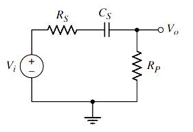
Calculation:
(i).
The value of coupling capacitor
The expression of lower cutoff frequency is:
(ii).
The transfer function of the circuit is determined as follows:
(b).
The value of the corner frequency
Answer to Problem 7.1EP
Explanation of Solution
Given Information:
The given circuit is shown below.
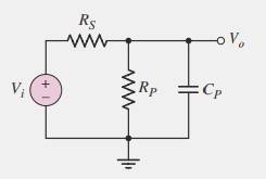
Calculation:
The value of time constant of the circuit is:
The value of corner frequency is determined as follows:
The transfer function of the circuit is determined as follows:
Want to see more full solutions like this?
Chapter 7 Solutions
Microelectronics: Circuit Analysis and Design


- Find theoretical expressions for the transfer function and cutoff frequencies of the circuit in figure 1. ( RL = 4.2k other values is up to you)arrow_forwardB) Express the following transfer function in term of its poles and zeros, then sketch the pole-zero diagram. Is the system stable? Why? 0.74 2²-2.544Z+2.5216 2² +0.64arrow_forwardProblem Solving Coverage: BJT Small Signal Analysis Instruction: WRITE the complete solutions and box your final answer. Use three (3) decimal places in your final answer. For the figure below: H 6.8 µF www ww 16 k2 16 2.2kQ 4. Solve the value of Zi, Zo, Av and Ai 6.8 µF HH 3-100 0.75 k 10µF Determine the following: A. DC Analysis: Determine the value of IE and VCE B. AC Analysis: 1. Draw/sketch the AC Equivalent Circuit using re model 2. Solve for re 3. Derive the equation of Zi, Zo, Av and Ai 5.6 karrow_forward
- Q4/ Determine the Nyquist rate for a continuous-time signal x(t) = 6 cos(50tt) + 20si n(300nt) – 10cos (100nt) ans. fs=300 Hzarrow_forwardFor the following statements, identify which are True and which are False. If False, please explainin one or two sentences why the statement is False.a) Resonance in an RLC series circuit occurs when the driving frequency is equal to 5 times the natural frequencyof the circuit.b) The maximum power is delivered when the system is being driven at resonance.c) Damped spring-mass oscillators and RLC series circuits do not behave mathematically identically. At all. Period. Please clear explainations. Thnak youarrow_forwardThe impedance value of an RLC circuit is 30 N (as maximum value), during a resonance with 60 Hz. BW is 20 Hz for the resonance point. a) Draw the circuit and calculate the R, L, C values. b) If we supply a signal with 50 Hz to this circuit, what do you think about the characteristic behavior of the circuit?arrow_forward
- 7.8. Consider an FIR highpass filter design with the following specifications: Stopband 0-1,500 Hz Passband 2,000-4,000 Hz Passband ripple 0.02 dB Stopband attenuation 60 dB Sampling rate = 8,000 Hz Determine the following: a. window method b. length of the FIR filter c. cutoff frequency for the design equation following specifications:arrow_forwardThe maximum phase shift that can be obtained by using a lead compensator with transfer function Ge(s) = = 4(1+0.15s) (1+0.05.s) equal toarrow_forwardFill in your bole algebra training with karnaugh in the image.(Do not discount.)arrow_forward
- In a series RLC circuit, the applied voltage is 120V. At resonance, the frequency is 200rad/sec, and the circuit current is 6.26 A. What is the resistance of the circuit (in Ohms)? (Use 2 decimal places. Unit is not required.)arrow_forwardThe block diagram for a modulator is provided in Figure 2. As can be seen, the modulated signal s(t) is obtained by taking the difference of in-phase and quadrature signals [wo(t) and w, (t) ]. The modulating signal is: m(t) = cos(Wm (t)). The two low pass filters have bandwidths equal to the first oscillator' frequency where fo > fm and unity gains. u(t) LPF vo(t) w.(t) Gain=1 B=f. 2cos(ar) s(t) m(t)=cos(@t) 2cos(as) -90° -90° Phase Shift Phase Shift LPF Gain=1 u;(t) B=f, V:(t) wi(t) (a) Determine the signals u, (t), vo(t), wo(t), u (t), v, (t), w, (t) and s(t) (b) What is the carrier frequency of RF signal in terms of w (c) Determine the complex envelope, s(t), of the signalarrow_forwardb. Choose the suitable choice foL ping of the following sentences 18 Maces 1. In order to tune a parallel resonant circuit to a lewer frequency the capacitor must a. Be increase. b. Be decrease. . BeZero. Remain the same 2. Ina very low frequency a series resonance behaves as Imost purely .......... circuit a Resistive. b Capacitive. . Inductive. d. Inductive and capacitive 3. Real part of the total impedance at resonance for complicated AC circuit is a. Positive Value. b. Zero Value. Negative Value. d. Complex value 4. For admittance locus the maximum obtained power factor is depend on a Maximum current b. Maximum voltage . Minimum power d. Minimum angle 5 Any non sinusoidal symmetrical waves are basically composite from fundamental wave plas .. of harmonics waves. aodd b. even . odd even d odd of even 6. If we append an inductance in series to an RL series circuit the time constant will be a Increases b. Decreases. Increases and Decreases. Increases or Decreases 7. The double energy…arrow_forward
 Introductory Circuit Analysis (13th Edition)Electrical EngineeringISBN:9780133923605Author:Robert L. BoylestadPublisher:PEARSON
 Delmar's Standard Textbook Of ElectricityElectrical EngineeringISBN:9781337900348Author:Stephen L. HermanPublisher:Cengage Learning
 Programmable Logic ControllersElectrical EngineeringISBN:9780073373843Author:Frank D. PetruzellaPublisher:McGraw-Hill Education
 Fundamentals of Electric CircuitsElectrical EngineeringISBN:9780078028229Author:Charles K Alexander, Matthew SadikuPublisher:McGraw-Hill Education
 Electric Circuits. (11th Edition)Electrical EngineeringISBN:9780134746968Author:James W. Nilsson, Susan RiedelPublisher:PEARSON
 Engineering ElectromagneticsElectrical EngineeringISBN:9780078028151Author:Hayt, William H. (william Hart), Jr, BUCK, John A.Publisher:Mcgraw-hill Education,